

UART configuration
This section describes the UART configuration for the Serial Modem application.
UART interface
A typical Serial Modem application configuration consists of a host processor connected to an nRF91 Series SiP through a UART interface. The UART connection serves as the physical transport layer, carrying both AT commands and PPP data frames for network communication.
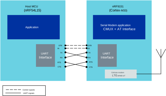
UART interface setup
The following UART signals are used:
Signal |
Direction |
Purpose |
|---|---|---|
TX/RX |
Bidirectional (crossed) |
Data transmission |
RTS/CTS |
Bidirectional (crossed) |
Hardware flow control |
DTR |
Host → Modem |
Data Terminal Ready - Host signals UART is powered on |
RI |
Modem → Host |
Ring Indicator - Modem wakes host for incoming data |
The Data Terminal Ready (DTR) and Ring Indicator (RI) signals are the control signals used for UART power management, while TX/RX/RTS/CTS are the standard UART signals.
Important
The use of Serial Modem without hardware flow control (RTS/CTS) is experimental and strongly not recommended. See Operating without hardware flow control for more information.
Board-specific pin mapping
The UART configuration varies depending on the board and whether it is running the Serial Modem application (nRF9151) or a host application (for example, nRF54L15).
UART configuration is done in the devicetree as a build time configuration.
Serial Modem application (nRF9151)
The following tables shows how to connect the UART pins to the corresponding pins on the nRF91 Series SiP:
UART Signal |
nRF9151 Pin |
|---|---|
TX |
P0.27 |
RX |
P0.26 (pull-up) |
RTS |
P0.14 |
CTS |
P0.15 (pull-up) |
DTR |
P0.08 (Button 1, pull-up, active high) |
RI |
P0.00 (LED1) |
UART instance: UART0 (VCOM0 on the interface chip)
Baud rate: 115200
Hardware flow control: Enabled
The DTR pin defaults to pull-up with an active high level, so the UART is always powered on. This pin is shared with Button 1, which you can use to manually toggle the DTR state. When the button is pressed, DTR is pulled low (inactive), powering down the UART.
The RI pin is connected to LED1, as it is not routed to the host PC.
This setup is default when building for nRF9151 DK without any overlay files.
UART Signal |
nRF9151 Pin |
|---|---|
TX |
P0.02 |
RX |
P0.03 (pull-up) |
RTS |
P0.06 |
CTS |
P0.07 (pull-up) |
DTR |
P0.31 (active low, pull-up) |
RI |
P0.30 (active low) |
UART instance: UART2
Baud rate: 115200
Hardware flow control: Enabled
On the nrf9151dk board, UART data and flow control pins (TX, RX, RTS, CTS) are on the P4 connector, while control signals (DTR, RI) are on the P3 connector.
The DTR pin defaults to pull-up, so the external MCU must assert DTR to power on the UART. When UART power management is not used, the DTR pin should be pulled to active state.
When hardware flow control is not used, remove hw-flow-control; from the uart2 node and remove the bias-pull-up from the CTS pin in the overlay.
With hardware flow control disabled, the UART peripheral does not monitor the CTS pin, so Serial Modem transmits unconditionally.
The CTS and RTS pins can be left unconnected.
See Operating without hardware flow control for further considerations.
This setup is provided in the app/external-mcu.overlay overlay file.
Note
DTR and RI pins use the P0.31 and P0.30 pins, which are shared with the I2C2 instance on the nrf9151dk board. I2C2 must stay disabled to use these pins for DTR and RI signals.
UART Signal |
nRF9151 Pin |
|---|---|
TX |
P0.00 |
RX |
P0.01 |
DTR |
P0.26 (Button 0, pull-up, active high) |
RI |
P0.30 (blue LED) |
UART instance: UART0 (VCOM0 on the interface chip)
Baud rate: 115200
Hardware flow control: Disabled
Hardware flow control is disabled, as there are no RTS/CTS pins on the Thingy:91 X interface chip.
The DTR pin defaults to pull-up with the active high level, so the UART is always powered on. This pin is shared with Button 0, which you can use to manually toggle the DTR state. When the button is pressed, DTR is pulled low (inactive), powering down the UART.
The RI pin is connected to the blue LED, which is used to indicate incoming data.
nRF91M1 pre-programmed Serial Modem application
nRF91M1 is a pre-programmed nRF9151 SiP that runs the Serial Modem application out of the box.
The pin mapping of the nRF91M1 follows the nrf9151dk board configuration. You can flash the nRF91M1 software to the nrf9151dk board for development and testing purposes.
The following table shows how to connect the UART pins to the corresponding pins on the nRF91M1 SiP:
Signal |
||
|---|---|---|
UART0 TX |
P0.27 |
45 |
UART0 RX |
P0.26 (pull-up) |
44 (pull-up) |
UART0 RTS |
P0.14 |
74 |
UART0 CTS |
P0.15 (pull-up) |
75 (pull-up) |
UART0 DTR |
P0.31 (active low, pull-up) (Wire to GND to power on the UART0) |
50 (active low, pull-up) |
UART0 RI |
P0.30 (active low) |
49 (active low) |
UART1 TX |
P0.29 |
48 |
AT UART:
UART instance: UART0 (VCOM0)
Baud rate: 115200
Hardware flow control: Enabled
Log / Trace UART:
UART instance: UART1 (VCOM1)
Baud rate: 1000000
Hardware flow control: Disabled
Important
When working with the nrf9151dk board with a PC host, the DTR pin must be wired to GND to power on the UART0. Currently, you must use a physical jumper wire, but in the future, the Board Configurator app can be used.
Important
The nRF91M1 firmware has hardware flow control permanently enabled and cannot be changed. When not using hardware flow control, the Serial Modem CTS pin must be wired to GND to allow Serial Modem to transmit. Without this, Serial Modem will see CTS as high (not clear to send) and will not transmit. See Operating without hardware flow control for further considerations.
By default in the nrf9151dk board, the UART0 is routed to VCOM0 on the interface chip, and UART1 is routed to VCOM1 on the interface chip. This allows the nrf9151dk board to be used with a PC host for development and testing.
When working with nrf9151dk board with an external MCU host, you must disable VCOM0 and VCOM1 in the Board Configurator app to release the UART pins for external use.
This setup is provided in the app/nrf91m1.overlay devicetree overlay file.
Host application
When using a PC serial terminal application (for example, PuTTY, Tera Term, minicom), build the Serial Modem application with the PC host. This is the default configuration when building for nRF9151 DK:
UART instance: VCOM0
Baud rate: 115200
Hardware flow control: CTS/RTS Enabled
Line terminator: CRLF
AT command terminator: CR
When configuring the serial terminal application, ensure that return key sends CR (Carriage Return) character as the line terminator. For incoming serial output from the modem, both CR and LF (Line Feed) characters are used. This is the most common configuration for AT command terminals.
This setup is the default for Tera Tearm, Putty, Minicom, and Picocom serial terminal applications.
The nRF54L15DK host applications use UART30 for Serial Modem communication:
UART Signal |
nRF54L15 Pin |
|---|---|
TX |
P0.00 |
RX |
P0.01 |
RTS |
P0.02 |
CTS |
P0.03 |
DTR |
P1.11 |
RI |
P1.12 |
UART0 on the P0 connector is the uart30 instance in the devicetree and is routed to VCOM0 on the interface chip.
This must be disabled in the Board Configurator app to release the UART pins for external use.
UART1 is routed to VCOM1 on the interface chip. The VCOM1 is used for console/shell.
RI and DTR signals are located on the P1 connector.
Note
Disable VCOM0 from Board Configurator app to release UART30 for Serial Modem.
For native simulator testing, UART2 is configured to use a host serial port:
uart2: uart2 {
    status = "okay";
    compatible = "zephyr,native-tty-uart";
    serial-port = "/dev/ttyACM0";
    current-speed = <115200>;
    hw-flow-control;

    modem: modem {
        compatible = "nordic,nrf91-slm";
        status = "okay";
        zephyr,pm-device-runtime-auto;
    };
};
Build the Serial Modem application with the PC host.
The UART0/VCOM0 from Serial Modem is assumed to be connected to /dev/ttyACM0 on the Linux host.
See the PPP shell sample for more information.
Controlling the UART power state
The Serial Modem application’s UART power state is controlled by the DTR signal. When DTR is asserted by the host, the UART is enabled and ready for communication. When DTR is deasserted, the UART is powered down to save power.
When the UART is powered down, it releases its high-speed clocks, which are then automatically stopped by the system’s power management. This achieves the lowest possible power consumption, as the UART is one of the primary power consumers in Serial Modem configurations. Power consumption can be reduced from hundreds of microamps to just a few microamps when the UART is powered down.
UART power management is completely independent of the modem power management (CFUN, PSM, eDRX, and so on). By actively managing the UART power state through DTR control, the nRF9151 SiP achieves ultra-low power consumption of approximately 2 µA when the cellular modem enters Power Saving Mode (PSM) and the UART is powered down. This is a reduction of over 99% compared to the 400-450 µA consumed when the UART remains active during idle periods. The nRF9151 SiP retains all the RAM content while in any of the power saving modes, so the application can resume from where it left off when the UART is powered up. Full network context is maintained, including socket connections, TLS/DTLS sessions, and so on. LTE connection is automatically resumed when there is outgoing data to be sent. No other GPIO control is required to utilize the PSM or eDRX modes.
Incoming data wake-up
When the UART is powered down and there is incoming data, the Serial Modem application asserts the RI pin to notify the host. The RI signal is handled by the modem driver on the host, which powers up the UART device and asserts the DTR line, signaling the Serial Modem that the UART is powered on and ready to receive data. The RI signal remains asserted until the nRF91 UART is activated and ready to transmit data.
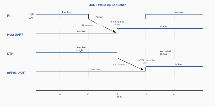
Sequence diagram showing the wake-up sequence when the UART is powered down
This sequence diagram illustrates the wake-up sequence when the UART is powered down. The RI signal triggers the host to power up its UART and assert DTR. Once the host UART is ready and DTR is asserted, the nRF91 enables its UART interface. The RI signal remains active throughout this process and only returns to inactive once the nRF91 UART is active. This coordinated wake-up ensures both ends of the communication link are ready before data transmission begins.
With hardware flow control - The host can observe its CTS pin (connected to Serial Modem’s RTS) to know when Serial Modem is ready to receive data. When Serial Modem starts driving its RTS pin, the host knows that Serial Modem is ready to receive. The host must also have a pull-up on its CTS pin.
Without hardware flow control- The host must monitor the RI signal, which is de-asserted when the Serial Modem UART becomes ready to receive data. Alternatively, the host can implement a sufficient timeout between asserting DTR and initiating its first TX operation. See Operating without hardware flow control for how to configure Serial Modem to transmit without hardware flow control.
Host-initiated wake-up
When the host processor needs to send data, it first powers up the UART device, then asserts the DTR signal to indicate that the UART is active. The modem detects the DTR assertion and powers up its UART interface, allowing communication to resume.
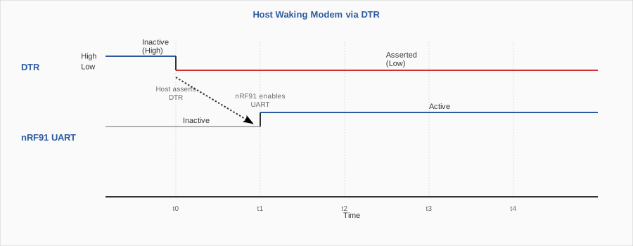
Sequence diagram showing host-initiated wake-up of the modem
Boot-up scenario
To boot-up the Serial Modem application, the host asserts ENABLE, DTR, and enables its UART (driving Serial Modem CTS low).
The Serial Modem firmware initializes within approximately 2000 ms, during which it activates its UART and asserts RTS to signal readiness.
Serial Modem then transmits a "Ready" message on TX, confirming that the link is operational.
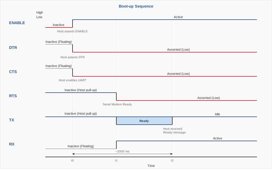
Signal sequence during boot-up
The ENABLE pin (pin 10 on the nRF9151 SiP) is a high-impedance control input for the nRF9151 internal power management unit (PMU). Driving it to a logic high powers on the SiP. Driving it to a logic low brings the device into an extremely low-current state. Any internal state not retained in non‑volatile memory is lost, and a full boot-up sequence is required when ENABLE is reasserted. See nRF9151 Hardware Design Guidelines — ENABLE for more information about the ENABLE pin.
Operating without hardware flow control
Important
The use of Serial Modem without hardware flow control (RTS/CTS) is experimental and strongly not recommended. Hardware flow control ensures reliable communication and prevents timing-related issues. Without hardware flow control, there is a risk of data loss in UART communication, especially in high-throughput scenarios.
The approach differs depending on whether you are using the pre-programmed nRF91M1 or a custom Serial Modem build.
Wire the CTS pin to GND — The nRF91M1 has hardware flow control permanently enabled. Wiring CTS to GND holds the line low, allowing Serial Modem to transmit.
Leave RTS unconnected — The RTS pin is not used and can be left floating.
Remove
hw-flow-control;from the UART node in the overlay — With hardware flow control disabled, the UART peripheral does not monitor CTS and Serial Modem transmits unconditionally.Remove the
bias-pull-upfrom the CTS pinctrl group in the overlay — This avoids a pull resistor drawing current against any external signal.Leave CTS and RTS unconnected — Neither pin is used and both can be left floating.
Key requirements:
The host must enable its own UART before asserting DTR.
To detect when Serial Modem is ready to receive, monitor the RI signal (de-asserted when ready) or use a sufficient timeout after DTR assertion.
See Incoming data wake-up for detailed timing information.
In boot-up scenarios, the host must wait for the
"Ready"message from Serial Modem before sending any data.
Buffer configuration:
Increase CONFIG_SM_UART_RX_BUF_SIZE and possibly CONFIG_SM_UART_RX_BUF_COUNT to provide sufficient buffer space for your use case.
Automatic UART power management using Zephyr’s Cellular Modem driver
As the Serial Modem’s UART interface power state is controlled by the DTR signal from the host, it is possible to automate the power management using Zephyr’s cellular modem driver with Zephyr’s CMUX (3GPP TS 27.010) module. This allows host applications to manage the UART power state automatically. See the Zephyr CMUX Power Saving documentation for more information. This configuration is completely done in the host. Serial Modem does not require any changes as it already follows the DTR signal state for UART power management.
You can configure the Zephyr’s cellular modem driver to automatically power on and off the UART device based on the data traffic on the CMUX DLCI channels.
This is done by setting the cmux-enable-runtime-power-save and cmux-close-pipe-on-power-save configuration options.
When PPP is connected, the UART is automatically powered down when the PPP connection is idle for a certain period of time (configurable with the cmux-idle-timeout-ms configuration option).
The following example shows how to configure automatic UART power management for the nRF54L15DK host application:
/* Zephyr modem UART <-> nRF91 Serial Modem UART */
&uart30 {
    status = "okay";
    current-speed = <115200>;
    hw-flow-control;
    zephyr,pm-device-runtime-auto;

    /* Nordic nRF91 Serial Modem configuration */
    modem: modem {
        compatible = "nordic,nrf91-slm";
        status = "okay";
        mdm-ring-gpios = <&gpio1 12 (GPIO_ACTIVE_LOW | GPIO_PULL_UP)>;
        mdm-dtr-gpios = <&gpio1 11 GPIO_ACTIVE_LOW>;
        zephyr,pm-device-runtime-auto;
        cmux-enable-runtime-power-save;
        cmux-close-pipe-on-power-save;
        cmux-idle-timeout-ms = <5000>;
    };
};
Key devicetree options:
zephyr,pm-device-runtime-auto: Enables automatic runtime power management for the UART devicecmux-enable-runtime-power-save: Enables CMUX power saving mechanismcmux-close-pipe-on-power-save: Closes the pipe when entering power save modecmux-idle-timeout-ms: Timeout in milliseconds before entering idle state (5000 ms in this example)
The setup above also required the CONFIG_PM_DEVICE_RUNTIME and CONFIG_PM_DEVICE_RUNTIME_ASYNC Kconfig options to be enabled.
When the cellular modem driver enters the idle state and there is no data to be sent or received on any DLCI channel, the UART device is powered down. When the cellular modem driver exits the idle state and there is data to be sent or received on any DLCI channel, the UART device is powered up.
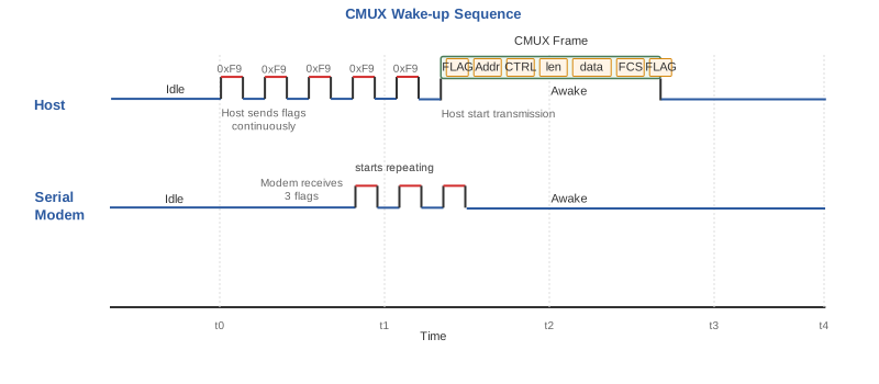
CMUX wake-up sequence showing flag character exchange
The CMUX wake-up sequence consists of the peer repeatedly sending flag characters (0xF9) on the UART.
The remote peer, upon detecting these flags, responds with its own flag character to indicate it is awake and ready to receive data.
This handshake ensures both ends of the communication link are synchronized before data transmission resumes.
As the flag characters carry no information, there is no issue of losing data when waking up.
When the peer that initiates the wake-up receives a flag character, it can continue by sending a valid frame.
Either end of the CMUX channel can initiate the wake-up procedure.
See the PPP shell sample for an example of how to configure the CMUX module to automatically power on and off the UART device based on the data traffic on the DLCI channels.