
Quick start guide
Note
Zigbee R22 is currently in maintenance mode, and it is not recommended to use it for new Zigbee designs. While critical bug fixes and security updates will be provided as necessary, it will not receive any enhancements or new features. The Zigbee R23 add-on represents Nordic’s primary solution for future Zigbee developments, offering improvements, support for new features, and support for the nRF52840 SoC and new platforms such as the nRF54L series.
This guide demonstrates some of the basic concepts of the Zigbee network using the Zigbee R22 add-on for the nRF Connect SDK and the nRF Connect for VS Code extension. It guides you through programming and testing of the required samples.
Overview
As part of this guide, you are going to program three Zigbee samples onto three different development kits in order to set up a basic Zigbee network composed of three devices, or nodes. A node is “a testable implementation of a Zigbee application on a single stack with a single network address, and on a single network”.
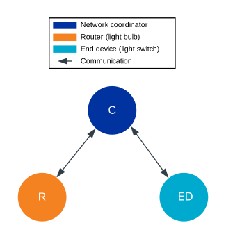
Zigbee star topology setup for this guide
The figure shows the Zigbee network star topology you are going to set up. See Zigbee topologies for more information.
Each of the samples you will use for forming the network is based on the single-chip, single-protocol architecture, uses the default configuration (that is, without any additional sample extensions enabled) and has a clearly defined role:
Zigbee network coordinator demonstrates the Zigbee Coordinator role and supports only the network steering commissioning mechanism.
Zigbee light bulb demonstrates the Zigbee Router role and implements the Dimmable Light device specification, as defined in the Zigbee Home Automation public application profile.
Zigbee light switch demonstrates the Zigbee End Device role and implements the Dimmer Switch device specification, as defined in the Zigbee Home Automation public application profile. Once commissioned into the network, it looks for devices with the implemented Level Control and On/Off clusters and can control the one that answers first.
All these samples also implement the Basic and Identify clusters, which are the basic Zigbee clusters.
Quick start requirements
For this quick start guide, you need three development kits of the following types:
Hardware platforms |
PCA |
Board name |
Board target |
|---|---|---|---|
PCA10056 |
|
||
PCA10100 |
|
||
PCA10095 |
|
||
PCA10112 |
|
You can mix different development kits.
Note
Make sure that you have three development kits before proceeding to the next steps.
Software requirements
For this quick start guide, install the following software:
Toolchain Manager - An application for installing the full nRF Connect SDK toolchain.
Microsoft’s Visual Studio Code - The recommended IDE for the nRF Connect SDK.
nRF Connect for VS Code extension - An add-on for Visual Studio Code that allows you to develop applications for the nRF Connect SDK.
SEGGER J-Link - Tool for handling the serial connection.
Set up the software
To set up the required software, follow the steps for the nRF Connect for VS Code extension described in Installing the nRF Connect SDK.
Program the samples
To program the samples, complete the following steps:
Open the nRF Connect for VS Code extension.
Complete the steps listed on the How to build an application page in the nRF Connect for VS Code extension documentation.
Program the application to the board:
Connect your development kit using the serial port.
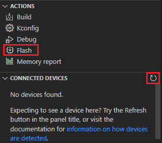
In the Connected Devices View, click Refresh Connected Devices. Your development kit appears on the list.
In the Actions View, click Flash.
When the programming is done, the LED 3 on the development kit turns on to indicate that the Zigbee network is open. After some time, it turns off and the Zigbee network needs to be reopened (see below).
Add the Zigbee light switch sample.
Repeat Steps 2 and 3 for the sample.
Add the Zigbee light bulb sample.
Repeat Steps 2 and 3 for the sample. The LED 4 turns on when the application is started.
Press Button 1 on the development kit programmed with the network coordinator sample to reopen the Zigbee network. After some time, the devices join the Zigbee network. On the development kit programmed with the light bulb sample, LED 3 turns on when the light bulb joins the network. On the development kit programmed with the light switch sample, LED 3 turns on when the device joins the network and LED 4 turns on when the light switch finds a light bulb to control.
- Reopening the network
If you find that you are having issues with your devices joining the Zigbee network, it may be because the network needs to be reopened manually. If the network is open, LED 3 on the development kit programmed with the network coordinator sample will be on. If LED 3 is not on, the network is closed and needs to be reopened.
To reopen the network, press Button 1 on the development kit that has been programmed as the network coordinator. By default, the network remains open for 180 seconds at startup, and after Button 1 is pressed. After 180 seconds, the network will close and will need to be reopened.
For more information, see the User interface section for the Zigbee Network coordinator sample.
Test the network
After forming the Zigbee network, test the interaction between the devices:
Press Button 2 once on the development kit programmed with the light switch sample to turn off the light bulb’s LED 4.
Press Button 1 once on the development kit programmed with the light switch sample to turn on the light bulb’s LED 4.
Press and hold Button 2 on the development kit programmed with the light switch sample to decrease the light bulb’s LED 4 brightness.
Press and hold Button 1 on the development kit programmed with the light switch sample to increase the light bulb’s LED 4 brightness.
Next steps
After you complete this quick start guide, we recommend that you get familiar with the following topics:
If you want to start configuring samples:
Zigbee sample variants - see the Zigbee samples pages.
If you want to test a multiprotocol solution, see the Multiprotocol Bluetooth LE extension section of the light switch sample.
If you want to start developing for co-processor designs:
If you want to learn more about ZBOSS:
ZBOSS user guide - see API documentation