sQSPI and FLPR counters
The sQSPI API translates the parameter nrf_sqspi_dev_cfg_t.sck_freq_khz into a value that can be used by FLPR’s internal counters.
The translation has the following constraints (assuming the SoC is running at highest base clock frequency):
The maximum core frequency of the device translates to a clock divider used in FLPR’s internal counters:
Timing parameters
When working with sQSPI, you should be aware of the associated timing parameters.
Symbol |
Description |
Min |
Typ |
Max |
Units |
|---|---|---|---|---|---|
FsQSPI,SCLK |
SCLK frequency |
64 |
MHz |
||
DCsQSPI,SCLK |
SCLK duty cycle |
50 |
% |
||
tDOV |
Data out valid |
2.2 |
ns |
||
tSDI |
Data in setup time |
11.7 |
ns |
Symbol |
Description |
Min |
Typ |
Max |
Units |
|---|---|---|---|---|---|
FsQSPI,SCLK |
SCLK frequency |
64 |
MHz |
||
DCsQSPI,SCLK |
SCLK duty cycle |
50 |
% |
||
tDOV |
Data out valid |
2.2 |
ns |
||
tSDI |
Data in setup time |
4.865 |
ns |
Symbol |
Description |
Min |
Typ |
Max |
Units |
|---|---|---|---|---|---|
FsQSPI,SCLK |
SCLK frequency |
80 |
MHz |
||
DCsQSPI,SCLK |
SCLK duty cycle |
50 |
% |
||
tDOV |
Data out valid |
ns |
|||
tSDI |
Data in setup time |
ns |
Note
Achieving 64MHz on nRF54L15 is possible when the slave access time plus the flight time of signal propagation is less than \(\frac{1}{64MHz} - t_{SDI}\). For example, to achieve 64MHz on nRF54L15 using GPIOHSPADCTRL gives a maximum slave access time of \(15.625ns - 4.865ns = 10.76ns\).
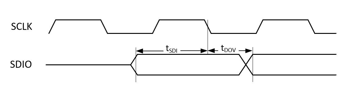
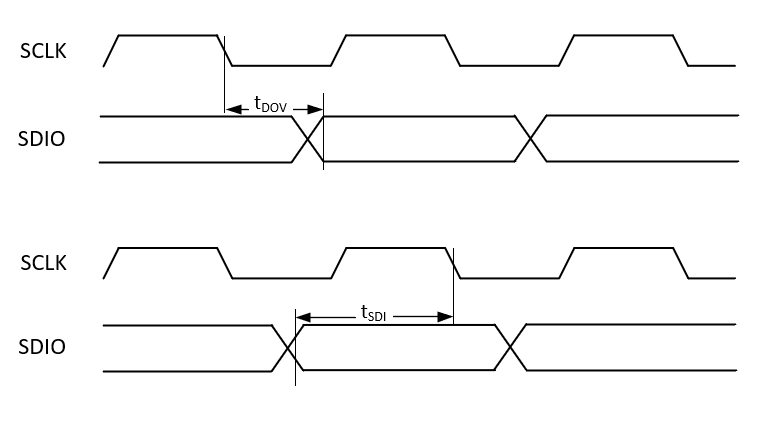
The following timing diagrams provide a visual reference to show how the parameters tDOV and tSDI relate to SCLK. SDIO represents the data lines.