Hardware requirements
To run and test the nRF Door Lock and Access Control applications, you must have the required hardware.
Development kit
Depending on the transport technology you want to use, the nRF Door Lock and Access Control applications support the following development kits (DK):
Hardware platforms |
PCA |
Board name |
Build target |
|---|---|---|---|
PCA10056 |
|
||
PCA10095 |
|
||
PCA10156 |
|
||
PCA10184 |
|
Configuring VDDIO voltage for nRF54L Series devices
The nRF54L15 DK and the nRF54LM20 DK operate at a default voltage level of 1.8V. Some expansion boards required for nRF Door Lock and Access Control applications with Aliro support require a higher voltage than the default. The recommended VDD setting depends on the development kit.
You can adjust the voltage for ports on the nRF54LM20 DK using the Board Configurator app.
Set VDD (nPM VOUT1) and VDDIO (nPM VOUT2) to 2.7V.
Note
Do not set the voltages above 2.7V on the nRF54LM20 DK. While 2.7V is sufficient for NFC reader expansion boards, higher voltages can interfere with the onboard LEDs.
See the recommended configuration for VDD (nPM VOUT1):
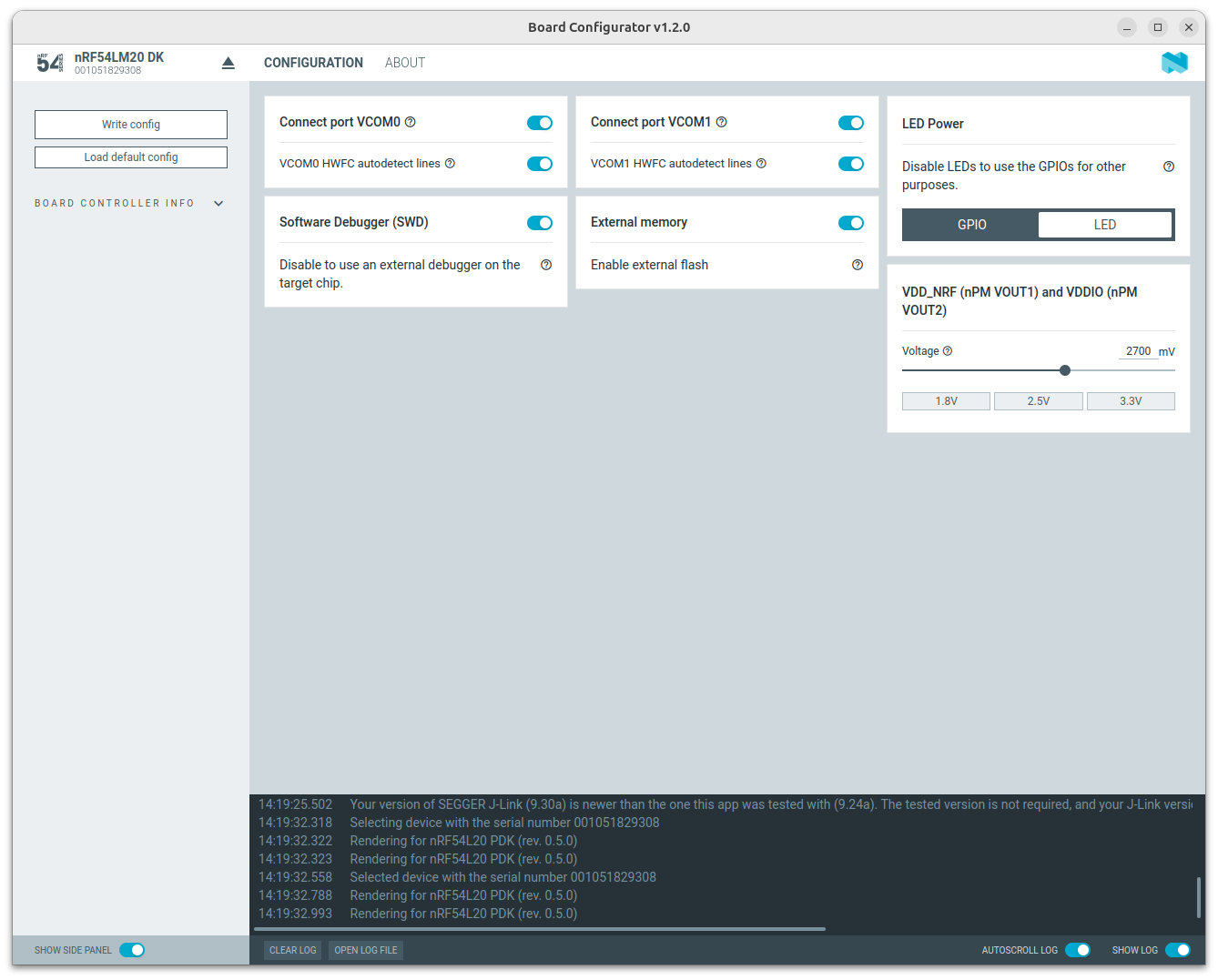
VDD board configuration.
You can adjust the voltage for ports on the nRF54L15 DK up to 3.3V using the Board Configurator app.
See the recommended configuration for VDD (nPM VOUT1):
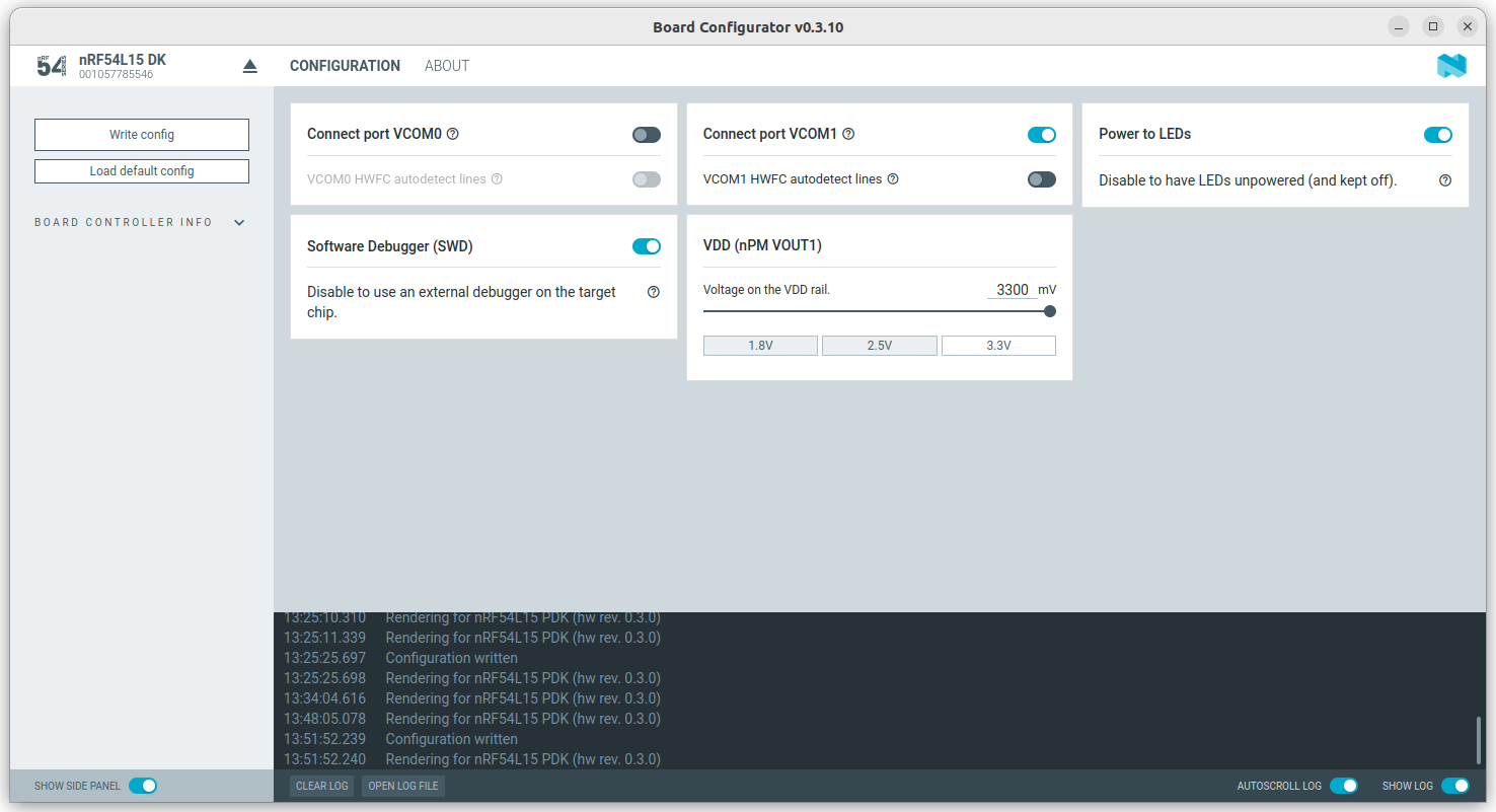
VDD board configuration.
Near Field Communication reader
To start working with the nRF Door Lock and Access Control applications with Aliro support, you must have at least one Near Field Communication (NFC) reader. The nRF Door Lock and Access Control Add-on supports the following NFC readers and their corresponding development expansion boards:
NFC reader |
NFC reader expansion board |
|---|---|
Note
The X-NUCLEO-NFC09A1 board requires a minimum of 2.7V to operate. Because of that, you must adjust the GPIO voltage for the nRF54L15 DK and the nRF54LM20 DK as outlined in the Configuring VDDIO voltage for nRF54L Series devices section.
Connecting the NFC reader
Follow the guidelines to connect the NFC reader expansion board based on your development kit:
The nRF54LM20 DK does not have Arduino-compatible header, therefore, you must connect your board using wires. To connect the NFC reader expansion board to the DK, refer to the following pin mapping. The pinout is applicable for each of the supported NFC reader expansion boards:
nRF54LM20 DK |
X-NUCLEO board |
|---|---|
P1.13 |
SCK MCU (D13) |
P1.12 |
MISO MCU (D12) |
P1.11 |
MOSI MCU (D11) |
P1.10 |
/SS MCU (D10) |
P1.14 |
IRQ MCU (A0) |
VBUS |
+5V |
VDDIO |
+3V3 |
GND |
GND |
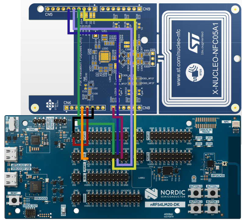
X-NUCLEO expansion board connection to the nRF54LM20 DK.
Note
To make the hardware setup easier, you can request the PCB design files of the Arduino-compatible adapters for the nRF54L15 DK and the nRF54LM20 DK via Nordic DevZone.
The nRF54L15 DK does not have Arduino-compatible header, therefore, you must connect your board using wires. To connect the NFC reader expansion board to the DK, refer to the following pin mapping. The pinout is applicable for each of the supported NFC reader expansion boards:
nRF54L15 DK |
X-NUCLEO board |
|---|---|
P1.13 |
SCK MCU (D13) |
P1.12 |
MISO MCU (D12) |
P1.11 |
MOSI MCU (D11) |
P2.08 |
/SS MCU (D10) |
P0.04 |
IRQ MCU (A0) |
VBUS |
+5V |
VDDIO |
+3V3 |
GND |
GND |
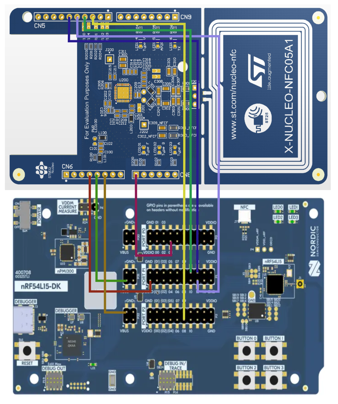
X-NUCLEO expansion board connection to the nRF54L15 DK.
Note
To make the hardware setup easier, you can request the PCB design files of the Arduino-compatible adapters for the nRF54L15 DK and the nRF54LM20 DK via Nordic DevZone.
The nRF5340 DK has P5 and P20 connectors located between their Arduino headers. These connectors might cause electrical shorts with the NFC reader expansion board, which can lead to NFC driver initialization failures and application crashes. To prevent shorts, ensure proper connection of the NFC reader expansion board and maintain adequate clearance between the connectors and the expansion board.
The nRF52840 DK has P5 and P20 connectors located between their Arduino headers. These connectors might cause electrical shorts with the NFC reader expansion board, which can lead to NFC driver initialization failures and application crashes. To prevent shorts, ensure proper connection of the NFC reader expansion board and maintain adequate clearance between the connectors and the expansion board.
Ultra-wideband (UWB) module
Aliro over the Bluetooth LE and UWB transport requires an external UWB module connected to the development kit, typically over SPI. This transport is supported on the nRF5340 DK and nRF54LM20 DK.
The core repository provides only the generic UWB abstraction. An external UWB provider module supplies the concrete radio driver, and that module determines which UWB module, expansion board, and wiring you need. Refer to the provider module’s documentation for the supported UWB hardware and pin mapping. For details on providing a UWB implementation, see Integrating a UWB implementation.
Note
By default, the applications in the nRF Door Lock and Access Control Add-on use the shared SPI configuration, which allows for concurrent use of the SPI bus by both the NFC Reader and the UWB module. Therefore, the NFC Reader and the UWB module can share the same Arduino header.
Test harness hardware
If you are developing a door lock with Aliro support, for testing purposes, use the official Aliro Certification Tool as a test harness. To set it up, you must first meet the test harness hardware requirements.