

NFC current measurements
This page describes how to measure NFC-related current consumption of an nRF Door Lock and Access Control Application using Power Profiler Kit II (PPK).
Note
The procedures, switch settings, and plots described on this page use an nRF5340 DK, an X-NUCLEO-NFC12A1 expansion board, and the Aliro standalone application in release configuration. Adapt the wiring and switch positions if you use different hardware.
Overview
The NFC current measurements are separated into two parts:
Choose the measurement based on what you want to analyze and optimize:
To check only the SoC current consumption, follow SoC current measurement.
To check only the NFC reader, follow NFC reader current measurement.
To evaluate the combined impact of both components, run both procedures separately and add or compare the results. The PPK cannot measure SoC and NFC module current in a single wiring setup.
The analysis covers two functional modes of the NFC reader:
IDLE — Average current over the full capture window with no NFC tag or User Device at the Reader (for example, a 60-second window).
ACTIVE — Average current while an NFC tag or User Device is held at the Reader during the capture window.
Prerequisites
Ensure you have the following hardware:
Power Profiler Kit II (PPK)
Development kit (for example, nRF5340 DK)
X-NUCLEO-NFC12A1 NFC reader expansion board
Ensure you have installed the following software:
nRF Connect for Desktop with the Power Profiler app
Build configuration
All measurements in this document were taken with the following build configuration for the Aliro standalone application:
west build -b nrf5340dk/nrf5340/cpuapp -p -- -DFILE_SUFFIX=release
In the Aliro standalone application, the release configuration keeps the UART shell enabled (used for provisioning the Aliro Reader). This adds background UART activity and can impact the measured current consumption.
Note
To remove UART-related current consumption, disable the UART node used by the shell or console in your DTS overlay, for example:
&uart0 {
        status = "disabled";
};
SoC current measurement
In this setup, the development kit is powered directly by the PPK, while the NFC module remains powered from the USB port.
Hardware connection
Connect the development kit and the PPK as shown in the following schematic:
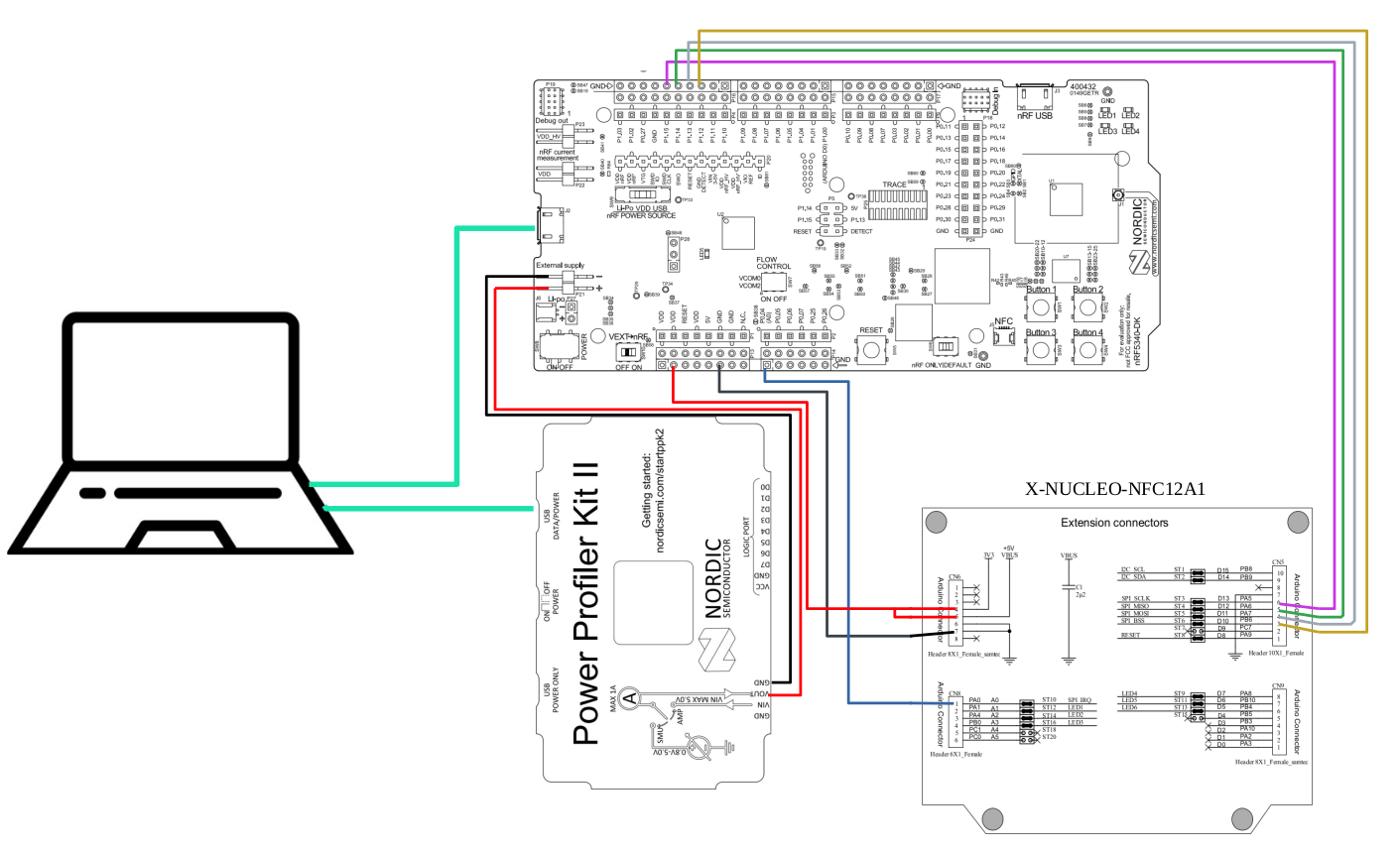
Development kit switch settings
Configure the development kit as follows for measurement:
POWER switch: ON
nRF power source: VDD
VEXT->nRF: ON
SW6 (nRF ONLY|DEFAULT): nRF ONLY (SEGGER, LEDs, and external flash powered off)
In the nRF ONLY mode, the external flash memory is powered down. Since the nRF Door Lock and Access Control Application uses external flash, it will not start correctly unless you power up the flash.
Whether the external flash current is included in the measurements depends on how it is powered:
Powered from VDD: excluded from the measurements
Powered from VDD nRF: included in the measurements
Choose one of the following approaches:
Full development kit current measurement — Set SW6 to nRF DEFAULT. This measures the full development kit current, including SEGGER, external flash, and other peripherals.
nRF SoC-only current measurement — Keep SW6 set to nRF ONLY, but power the external flash from VDD. This allows the application to run while minimizing additional current paths. This option requires a hardware modification of your development kit:
Reconfigure the external flash power source solder bridges so that the flash is powered from VDD:
SB16 (VDD_PER): OPEN (remove the solder bridge)
SB17 (VDD): SHORT (add a solder bridge)
SB18 (VDD_nRF): OPEN
For details on external memory, see the datasheet of your device (for example, nRF5340 DK external memory).
All measurements in this document were taken using the nRF SoC-only current measurement approach.
Power Profiler Kit II settings
Configure the Power Profiler Kit II as follows:
Mode: Source Meter
Supply voltage:
3000mVSampling rate:
100 000samples per secondCapture duration:
60s
Procedure
Complete the following steps:
Connect the PPK to your development kit as the power source.
Program the device under test (DUT):
Use the option that matches your hardware setup. Switch positions differ during flashing and during measurement.
Power up external flash using VDD.
Set switches to VEXT OFF and nRF DEFAULT.
Flash the firmware built in Build configuration.
Set switches to VEXT ON and nRF ONLY for measurement.
Set switches to VEXT OFF and nRF DEFAULT.
Enable PPK power output.
Flash the firmware built in Build configuration.
Enable PPK power output.
Start the capture in Power Profiler.
For IDLE mode, do not present a tag or User Device at the Reader. For ACTIVE mode, hold an NFC tag or User Device at the Reader for the capture window.
After 60 seconds, the measurement ends automatically. You can also stop it manually.
NFC reader current measurement
In this setup, the NFC module is powered from the development kit, while the development kit itself is powered through USB. The PPK measures only the NFC module current.
Hardware connection
Connect the development kit and the PPK as shown in the following schematic:
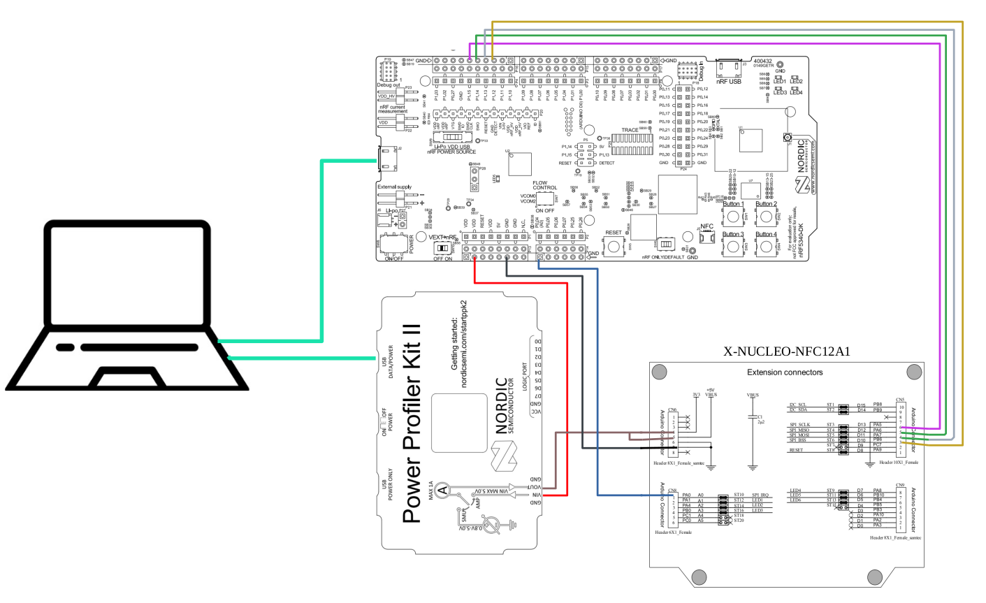
Development kit switch settings
Configure the development kit as follows:
POWER switch: ON
nRF power source: VDD
VEXT->nRF: OFF
SW6 (nRF ONLY|DEFAULT): nRF DEFAULT
Power Profiler Kit II settings
Configure the Power Profiler Kit II as follows:
Mode: Ampere Meter
Capture duration:
60s
Procedure
Power the development kit using USB.
Flash the firmware built in Build configuration.
Connect the PPK in series between the development kit VDD and the NFC module power input, as shown in the schematic above.
Start the capture in the Power Profiler app.
For IDLE mode, do not present a tag or User Device at the Reader. For ACTIVE mode, hold an NFC tag or User Device at the Reader for the capture window.
After 60 seconds, the measurement ends automatically. You can also stop it manually.
Analyzing results
The following figures show current consumption captured on an nRF5340 DK with an X-NUCLEO-NFC12A1 expansion board using the build configuration described above.
IDLE mode
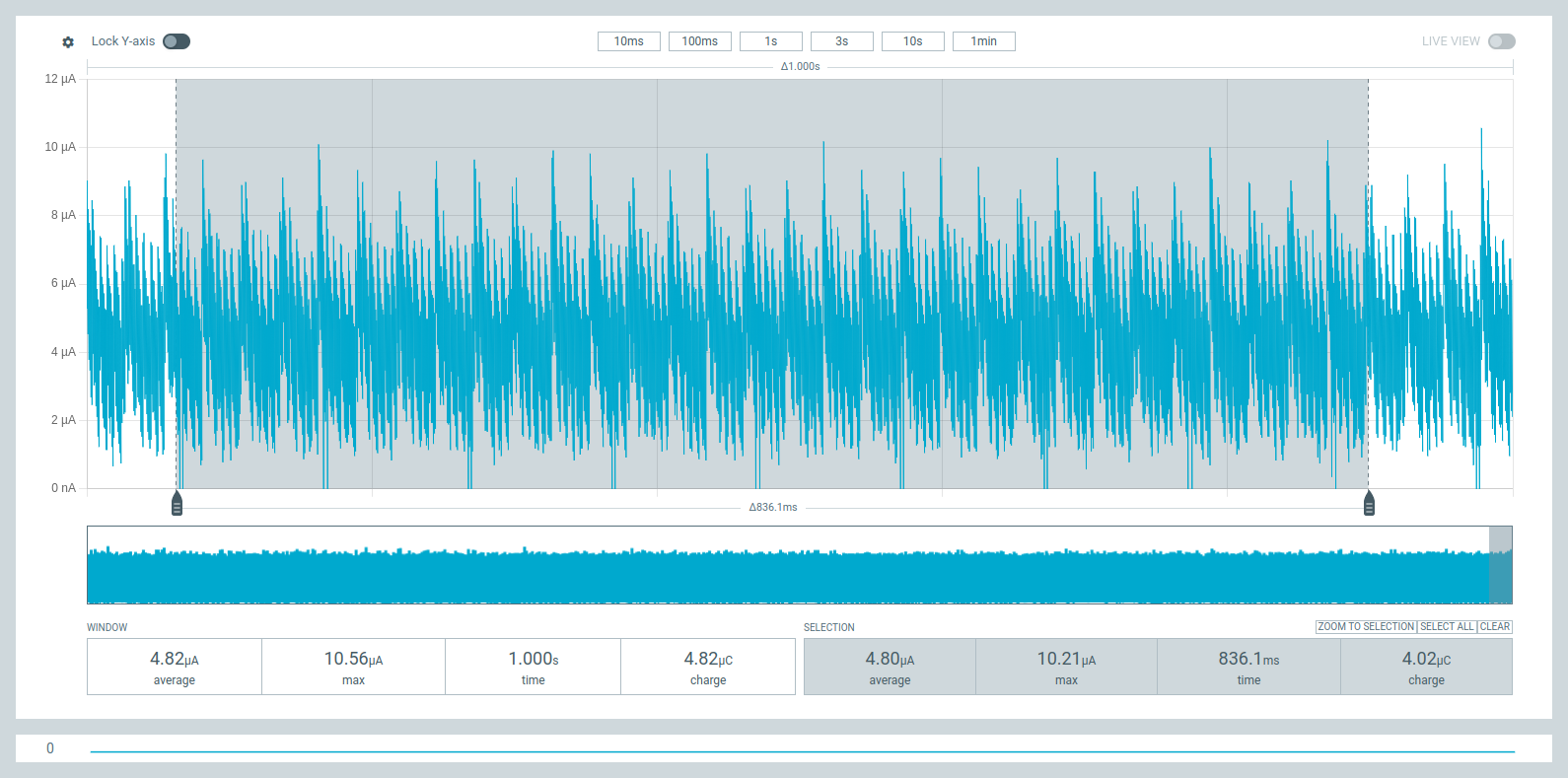
nRF5340 SoC current consumption in IDLE mode (SoC measurement setup).
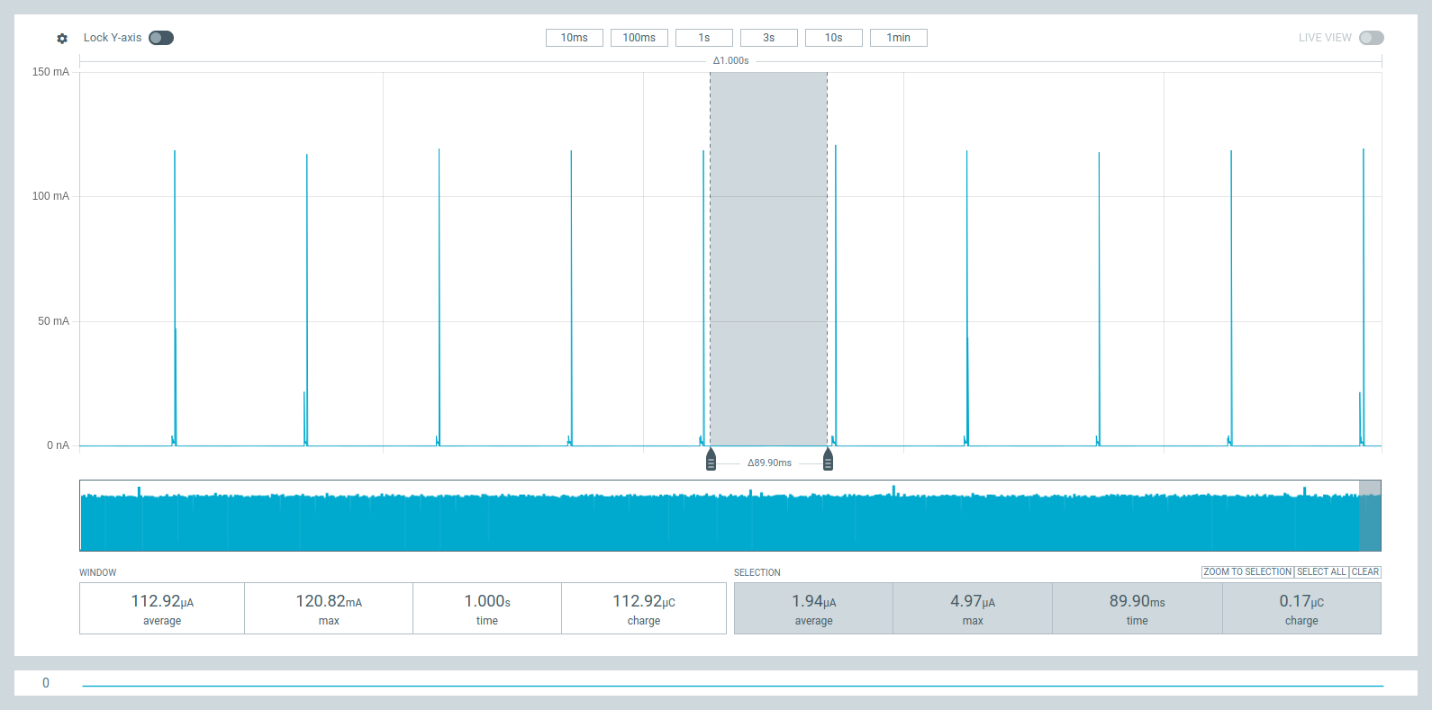
X-NUCLEO-NFC12A1 NFC module current consumption in IDLE mode (NFC reader measurement setup).
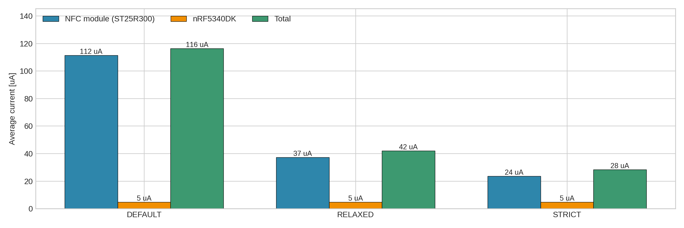
Average NFC module current in IDLE mode depending on wake-up mode configuration.
In IDLE mode, the X-NUCLEO-NFC12A1 module current consumption depends on the CONFIG_RFAL_WAKE_UP_MODE Kconfig choice.
This option adjusts RFAL driver settings that control the wake-up procedure.
Among other effects, it changes RFAL_WUM_PERIOD (wake-up timer period; how often wake-up measurements are performed) in the wakeupConfig structure, which affects average current consumption in IDLE mode.
See NFC integration in the reference applications for the available wake-up mode options and drivers/nfc/stm/nfc_configs/Kconfig for option definitions.
ACTIVE mode
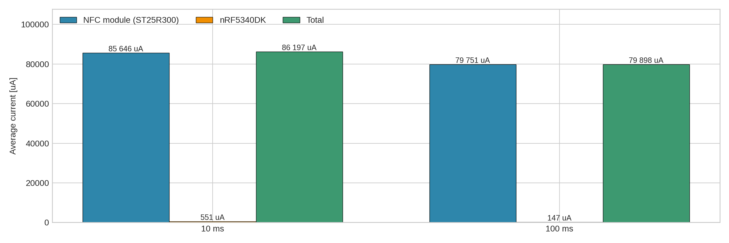
nRF5340 SoC average current in ACTIVE mode depending on CONFIG_RFAL_NFC_WORKER_INTERVAL_MS.
In ACTIVE mode, development kit current consumption depends on CONFIG_RFAL_NFC_WORKER_INTERVAL_MS (the time between consecutive NFC worker executions).
Configure it in applications/*/src/aliro/platform/nfc/Kconfig.
However, the largest source of total current in this mode is the NFC module itself.
RFO tuning
The RF output (RFO) driver resistance has a significant impact on NFC module current consumption in ACTIVE mode. Increasing the RFO output resistance multiplier reduces NFC module current in ACTIVE mode, but it also reduces sensitivity and read range.
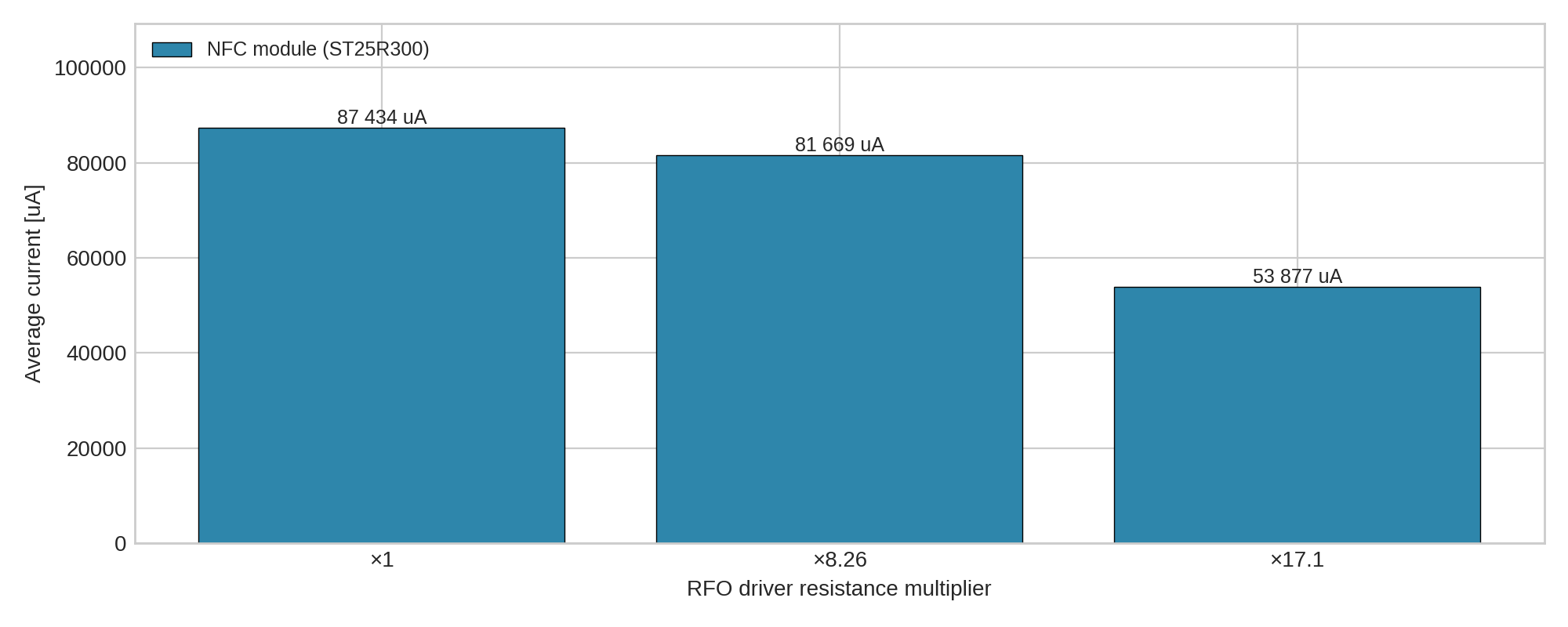
X-NUCLEO-NFC12A1 average current in ACTIVE mode depending on RFO driver resistance multiplier.
You can configure the RFO driver resistance using the RFAL API:
rfalChipSetRFO(uint8_t rfo);
The rfo parameter is a value from 0 (lowest output resistance) to 15 (highest output resistance).
For details, see the ST25R300 datasheet.
Other parameters also affect NFC current consumption.
You can find them in applications/*/src/aliro/platform/nfc/Kconfig and drivers/nfc/stm/nfc_configs/Kconfig.
For example, RFAL_WAKEUP_NPOLLS controls how many polling cycles are performed before and after Wake-Up mode, which can impact average NFC module current in ACTIVE mode.
See the RFAL documentation for more details.