
Bluetooth: Direct Test Mode
This sample enables the Direct Test Mode functions described in Bluetooth® Core Specification (Vol. 6, Part F). The actual encoding of the test commands and events is described in sections 3.3 and 3.4, respectively, of Vol. 6, Part F of this specification document.
Requirements
The sample supports the following development kits:
Hardware platforms |
PCA |
Board name |
Shields |
|
|---|---|---|---|---|
nRF54LV10 DK |
PCA10188 |
|
||
nRF54LS05 DK |
PCA10214 |
nrf54ls05dk |
|
|
PCA10184 |
|
|||
nRF54LC10 DK |
PCA10226 |
nrf54lc10dk |
|
|
PCA10156 |
|
|
||
PCA10156 |
|
|||
PCA10156 |
|
|||
PCA10175 |
|
|||
PCA10095 |
|
|
||
PCA10056 |
|
|||
PCA10112 |
|
Additionally, the sample requires one of the following testing devices:
Dedicated test equipment, like an Anritsu MT8852 tester. See Testing with a certified tester.
Another development kit with the same sample. See Testing with another development kit.
A computer with the Direct Test Mode app available in the nRF Connect for Desktop. See Other testing options.
Overview
The sample uses Direct Test Mode (DTM) to test the operation of the following features of the radio:
Transmission power and receiver sensitivity
Frequency offset and drift
Modulation characteristics
Packet error rate
Intermodulation performance
Test procedures are defined in the document Bluetooth Low Energy RF PHY Test Specification.
You can carry out conformance tests using dedicated test equipment, such as the Anritsu MT8852 or similar, with an nRF5 running the DTM sample set as device under test (DUT).
Implementation
The sample uses the DTM 2-wire UART to HCI Converter library to convert between 2-wire UART commands and events and Bluetooth LE HCI commands and events. It also implements a transport module that uses Zephyr UART APIs to read and write 2-wire commands and events on the UART interface.
The sample application in src/main.c runs the following loop:
Wait for a 2-wire UART command using the
dtm_tw_transport_read()function.Call the
dtm_tw_to_hci_process_tw_cmd()function.If the result is a 2-wire event, send the event immediately on UART using the
dtm_tw_transport_write()function.If the result is an HCI command, send it through
bt_send(), wait for the HCI event, generate the appropriate 2-wire event using thedtm_tw_to_hci_process_hci_event()function, then send the produced 2-wire event usingdtm_tw_transport_write().
This follows the conversion flow defined by the DTM conversion library.
Debugging
In this sample, the UART console is used to exchange commands and events defined in the DTM specification. Debug messages are not displayed in the UART console. Instead, they are printed by the RTT logger.
If you want to view the debug messages, follow the procedure in Testing and optimization. For more information about debugging in the nRF Connect SDK, see Debugging an application.
Note
The default configuration disables all logging, so you need to enable the logging options to view the debug messages. See the Configuration section for details.
Configuration
See Configuring and building for information about how to permanently or temporarily change the configuration.
Configuration options
The default sample configuration is in the prj.conf file.
To enable RTT logging for this sample, set the following Kconfig options:
CONFIG_LOG=y
CONFIG_LOG_PRINTK=y
CONFIG_USE_SEGGER_RTT=y
CONFIG_LOG_BACKEND_RTT=y
To set the log level for the transport module, set one of the following Kconfig options:
CONFIG_DTM_TW_TRANSPORT_LOG_LEVEL_DBGfor log level DEBUGCONFIG_DTM_TW_TRANSPORT_LOG_LEVEL_INFfor log level INFOCONFIG_DTM_TW_TRANSPORT_LOG_LEVEL_WRNfor log level WARNINGCONFIG_DTM_TW_TRANSPORT_LOG_LEVEL_ERRfor log level ERRORCONFIG_DTM_TW_TRANSPORT_LOG_LEVEL_OFFto disable logging
Further configuration options are available for the DTM 2-wire UART to HCI conversion library. See DTM 2-wire UART to HCI Converter for details.
Building and running
This sample can be found under samples/bluetooth/direct_test_mode in the nRF Connect SDK folder structure.
To build the sample, follow the instructions in Building an application for your preferred building environment. See also Programming an application for programming steps and Testing and optimization for general information about testing and debugging in the nRF Connect SDK.
Note
When building repository applications in the SDK repositories, building with sysbuild is enabled by default.
If you work with out-of-tree freestanding applications, you need to manually pass the --sysbuild parameter to every build command or configure west to always use it.
Note
On the nRF5340 development kit, this sample requires the nRF5340: Remote IPC shell sample on the application core. The Remote IPC shell sample is built and programmed automatically by default.
Testing
After programming the sample to your development kit, you can test it in two main scenarios, as described in the following chapters.
Note
For the nRF5340 DK board (PCA10095), see Getting logging output with nRF5340 DK for information about the COM terminals on which the logging output is available.
Testing with a certified tester
Conformance testing is performed using a certified tester, such as Anritsu MT8852. The setup and test procedures depend on the tester used. Details about the test operation are available in the tester documentation. The tester handles sending DTM test commands and reading transmitted signals or sending received signals.
The application note nAN34 describes two alternatives for setting up a production test with DTM using one of our old devices.
Testing with another development kit
To test with another development kit running the same sample, you need to send DTM 2-wire UART commands to the kits. You can send these commands using one of the following methods:
Other testing options
Option A: Using the Direct Test Mode app
The Direct Test Mode app in nRF Connect for Desktop generates and sends commands automatically.
Connect both development kits to the computer using a USB cable.
Start the Direct Test Mode app in nRF Connect for Desktop and select one of the development kits.
Set the Transmitter mode and configure the test parameters (frequency, packet pattern, length, etc.). For example, use channel 37 (2402 MHz) with
10101010packet pattern and 37-byte packet length.Start the test. The app will send the
TRANSMITTER_TESTcommand to the kit.Observe the
TEST_STATUS_EVENTresponse with the SUCCESS status field.On the second kit, start the Direct Test Mode app and select it in the application.
Set the Receiver mode with matching test parameters.
Start the test. The app will send the
RECEIVER_TESTcommand to the kit.Observe the
TEST_STATUS_EVENTresponse and the packet count increasing on the application chart.Stop the test on the receiver kit, and observe the
PACKET_REPORTING_EVENTwith the received packet count.Swap roles and repeat the test in the reverse direction.
Option B: Sending raw DTM commands
You can send raw DTM 2-wire UART commands using, for example, a serial terminal emulator. See Direct Test Mode terminal connection for the required serial port settings and command format.
Connect both development kits to the computer using a USB cable. The computer assigns to each development kit a serial port. Serial ports are referred to as COM ports on Windows, /dev/ttyACM devices on Linux, and /dev/tty devices on macOS. To list Nordic Semiconductor devices connected to your computer together with their serial ports, open a terminal and run the
nrfutil device listcommand. Alternatively, check your operating system’s device manager or its equivalent.Connect both kits with a terminal emulator. See Direct Test Mode terminal connection for the required settings.
Start
TRANSMITTER_TESTon one kit by sending the0x80 0x96DTM command. This command will trigger TX activity on the 2402 MHz frequency (1st channel) with10101010packet pattern and 37-byte packet length.Observe that you received the
TEST_STATUS_EVENTpacket in response with the SUCCESS status field:0x00 0x00.Start
RECEIVER_TESTon the second kit by sending the0x40 0x96DTM command. Command parameters are identical to the ones used for theTRANSMITTER_TESTcommand.Observe that you received the
TEST_STATUS_EVENTpacket in response with the SUCCESS status field:0x00 0x00.Finish RX testing on the second kit using the
TEST_ENDDTM command by sending the0xC0 0x00packet.Observe that you received the
PACKET_REPORTING_EVENTpacket in response, indicated by the most significant bit set to1. The other 15 bits of the event contain the number of received packets, which means you can subtract0x8000from the event (big endian) to get the packet count. For example, the0xD6 0xACmessage indicates that 22188 radio packets have been received.Experiment with other combinations of commands and their parameters. The protocol is defined in Bluetooth Core Specification Vol. 6, Part F, 3 UART Test Interface.
To test the reverse direction, swap the TX and RX roles between the two kits and repeat the process.
Direct Test Mode terminal connection
To send commands to and receive responses from the development kit that runs the Direct Test Mode sample, connect to it with RealTerm in Windows or Minicom in Linux.
The Bluetooth Low Energy DTM UART interface standard specifies the following configuration:
Eight data bits
No parity
One stop bit
No hardware flow control
A selection of bit rates from 9600 to 1000000, one of which must be supported by the DUT. It might be possible to run other bit rates by experimenting with parameters.
Note
The default bit rate of the DTM UART driver is 19200 bps, which is supported by most certified testers.
When using a 2-wire interface, you must send all commands as two-byte HEX numbers. The responses must have the same format.
Connect with RealTerm (Windows)
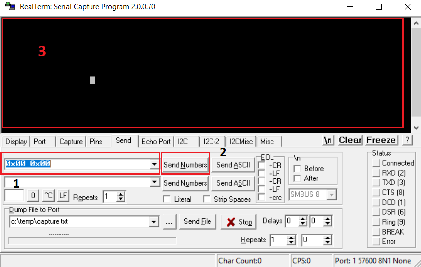
The RealTerm terminal program offers a graphical interface for setting up your connection.
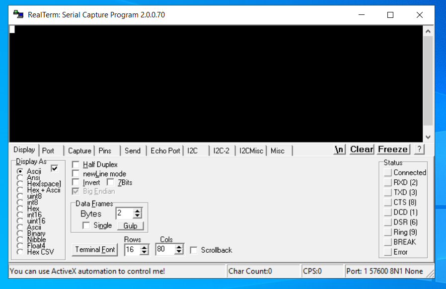
The RealTerm start window
To test DTM with RealTerm, complete the following steps:
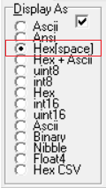
On the Display tab, set Display As to Hex[space].
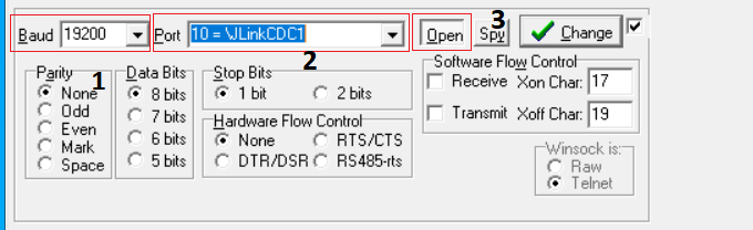
Open the Port tab and configure the serial port parameters:
Set the Baud to
19200(1).Select your J-Link serial port from the Port list (2).
Set the port status to
Open(3).
Open the Send tab:
Write the command as a hexadecimal number in the field (1). For example, write
0x00 0x00to send a Reset command.Click the Send Numbers button (2) to send the command.
Observe the response in the DTM in area (3). The response is encoded as hexadecimal numbers.
Connect with Minicom (Linux)
Minicom is a serial communication program that connects to the DTM device.
On the Linux operating system, install a Minicom terminal. On Ubuntu, run:
sudo apt-get install minicom
Run the Minicom terminal:
sudo minicom -D DTM serial port -s
For example:
sudo minicom -D /dev/serial/by-id/usb-SEGGER_J-Link_000683580193-if00 -sThe -s option switches you to Minicom setup mode.
Configure the Minicom terminal:
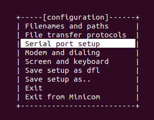
Configuration window
Select Serial port setup and set UART baudrate to
19200.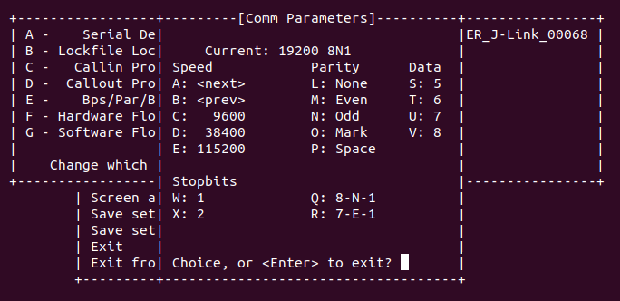
Select Screen and keyboard and press S on the keyboard to enable the Hex Display.
Press Q on the keyboard to enable Local echo.
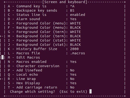
Minicom is now configured for receiving data. However, you cannot use it for sending DTM commands.
Send DTM commands:
To send DTM commands, use
echowith-neoptions in another terminal. You must encode the data as hexadecimal numbers (xHH, byte with hexadecimal value HH, 1 to 2 digits).sudo echo -ne "encoded command" > DTM serial port
To send a Reset command, for example, run the following command:
sudo echo -ne "\x00\x00" > /dev/serial/by-id/usb-SEGGER_J-Link_000683580193-if00
Limitations
This sample inherits the limitations of the DTM 2-wire UART to HCI conversion library. See DTM 2-wire UART to HCI Converter (section Limitations).
Dependencies
This sample uses the following nRF Connect SDK library:
In addition, it uses the following Zephyr libraries: