Test setup
An overview of software test samples, hardware development platforms, test modes, and firmware configurations is provided to help prepare your device for regulatory testing.
Test samples
You can use the software test samples available in the nRF Connect SDK for regulatory testing of the nRF70 Series devices.
Wi-Fi Radio test sample
The Wi-Fi® Radio test sample is used to configure and control the Wi-Fi radio on the nRF70 Series device. The Wi-Fi Radio test firmware supports the configuration of the Wi-Fi radio in specific modes and with various TX and RX parameters to test its performance.
For an overall description, see either the Wi-Fi: Radio test (Multi domain) sample or the Wi-Fi: Bluetooth LE Wi-Fi Radio test (Single domain) sample. The sub-commands that can be used to configure the radio are described in Wi-Fi Radio test subcommands. For more information on using the sample for regulatory testing, see Using the Wi-Fi Radio test sample.
Wi-Fi Shell sample
The Wi-Fi Shell sample runs on the Device Under Test (DUT) and allows the control of Wi-Fi functionality through a shell interface. The sample allows the DUT to connect to a Wi-Fi access point device and expose a shell interface through a UART console to run relevant Wi-Fi Shell commands.
The Wi-Fi Shell sample has an option to set a static IP address for the DUT at build time by configuring the prj.conf file.
If the Dynamic Host Configuration Protocol (DHCP) resolution fails, this IP address will be used by the device when connecting to the access point.
For an overall description, see Wi-Fi: Shell sample. For more information on using the sample for regulatory testing, see Using the Wi-Fi Shell sample.
Wi-Fi Station sample
The Wi-Fi Station (STA) sample demonstrates how to add Wi-Fi functionality to applications programmatically. The sample allows the DUT to connect to a Wi-Fi access point device and gives visual indication of a connected state through a blinking LED and of a not connected state through the LED not lighting up.
The Wi-Fi Station sample has an option to set a static IP address for the DUT at build time by configuring the prj.conf file.
If the DHCP resolution fails, this IP address is used by the device when connecting to the access point.
For an overall description, see Wi-Fi: Station sample. For more information on using the sample for regulatory testing, see Using the Wi-Fi Station sample.
Radio test (short-range) sample
The Radio test (short-range) sample demonstrates how to configure and test the performance of a 2.4 GHz radio (Bluetooth® Low Energy, IEEE 802.15.4 and proprietary).
The Radio test firmware supports the configuration of 2.4 GHz radio in specific modes and with various TX and RX parameters to test its performance.
For an overall description, see Radio test (short-range) sample. For more information on using the sample for regulatory testing, see Using the Radio test (short-range) sample.
Test hardware
Use the nRF70 Series hardware development platforms for regulatory testing.
The nRF70 Series includes the following platforms:
nRF7002 Development Kit (DK) – A single-board solution featuring the Wi-Fi 6 capabilities of the nRF7002 companion IC and the nRF5340 System on Chip (SoC).
nRF7002 Evaluation Kit (EK) – A shield board used for evaluating the nRF7002 companion IC. The EK is compatible with the nRF52840, nRF5340, and nRF91 DKs through its Arduino connector.
For hardware information, see the user guides nRF7002 DK Hardware and nRF7002 EK Hardware. For more information on the boards in nRF Connect for Desktop, see Getting started with nRF70 Series.
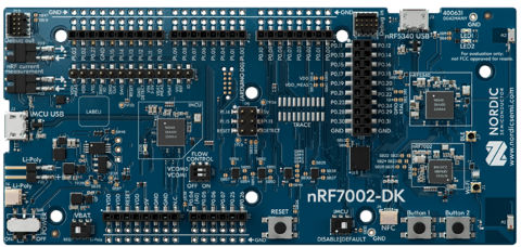
nRF7002 DK, top view
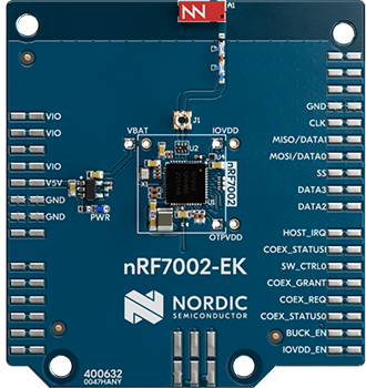
nRF7002 EK, top view
Test modes
Set up the nRF70 Series hardware development platforms in test configurations for both non-signaling and signaling mode. These two test modes are used to execute regulatory certification test cases.
Non-signaling mode
This section describes Wi-Fi test setup using applications that do not require the nRF7002 device to be associated with an access point or test equipment supporting Wi-Fi access point mode.
TX test setup for packet generation
The following testbed setup is used for performing Wi-Fi and short-range RF based transmitter testing.

Testbed setup for RF based transmitter testing
RX test setup for PER measurement
The following testbed setup is used for performing Wi-Fi and short-range Packet Error Rate (PER) based TX/RX testing.

Testbed setup for PER based TX/RX testing
As an alternative, you can replace the TX-DUT with an appropriate Vector Signal Generator (VSG), for example Rohde and Schwarz CMW-500.
TX test setup for adaptivity testing
For information on TX testing (adaptivity), see EN 301 893 V2.1.1 based adaptivity test procedure.
Signaling mode
This section describes Wi-Fi test setup using applications that require the nRF7002 to be associated with an access point or test equipment supporting Wi-Fi Access Point mode.

Testbed setup with access point
Firmware setup
This describes the flashing, running, and use of the appropriate console ports while using test applications on the nRF7002 DK or EK.
Programming firmware in the nRF7002 setup
This procedure uses the nRF Util tool, which is part of the nRF Connect SDK toolchain bundle and you get it when you Install the nRF Connect SDK code and toolchain.
To program firmware in the nRF7002 DK or EK setup, complete the following steps.
Connect your computer to the nRF7002 kit with a USB cable.
Switch the nRF7002 kit ON.
Open a command prompt window.
If the read back protection mechanism on the DK or EK is enabled, use the following command to unlock the device and disable the read back protection mechanism before loading the firmware:
$ nrfutil device recover
Note
Firmware loading returns an error if the read back protection mechanism is enabled.
To program the relevant hex (binaries) to the application core on the nRF7002 DK or EK, copy in the following commands excluding the dollar sign:
For Wi-Fi Radio test in combined mode:
$ nrfutil device program --firmware merged.hex --core Application --options chip_erase_mode=ERASE_ALL,reset=RESET_SYSTEM
For Station (STA), Shell, and stand-alone Wi-Fi Radio test samples:
$ nrfutil device program --firmware merged.hex --core Application --options chip_erase_mode=ERASE_ALL,reset=RESET_SYSTEM
Program the relevant hex (binaries) to the network core on the nRF7002 DK:
$ nrfutil device program --firmware merged_CPUNET.hex --core Network --options chip_erase_mode=ERASE_ALL,reset=RESET_SYSTEM
To run the firmware on the nRF7002 DK or EK, reset the device. You can press the RESET button, use the
nrfutil device resetcommand in nRF Util, or power cycle the development kit.Note
Set the baud rate to 115,200 bps. For more information, see VCOM settings.
VCOM settings
Complete the following steps to set the VCOM settings for the nRF7002 DK or EK:
Connect your computer to the nRF7002 board with a USB cable.
Use the default baud rate (115200) for testing.
Serial ports are referred to as COM ports on Windows, /dev/ttyACM devices on Linux, and /dev/tty devices on macOS. To list Nordic Semiconductor devices connected to your computer together with their serial ports, open a terminal and run the
nrfutil device listcommand. Alternatively, check your operating system’s device manager or its equivalent. Typically, VCOM0 is connected to the nRF5340 network core running a Radio test (short-range) and VCOM1 is connected to the nRF5340 application core running a Wi-Fi Radio test.Verify the mapping of the serial ports based on the available commands for each port. See the following code example and figures:
$ nrfutil device list
1050753610
product         J-Link
board version   PCA10143
ports           /dev/ttyACM4, vcom: 0   // This is for Radio Test, note baud rate is 115200bps
                /dev/ttyACM5, vcom: 1   // This is for Wi-Fi Radio Test, note baud rate is 115200bps
traits          devkit, jlink, seggerUsb, serialPorts, usb

Supported devices found: 1
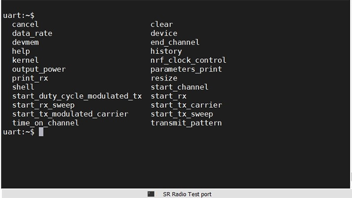
Short-range Radio test port
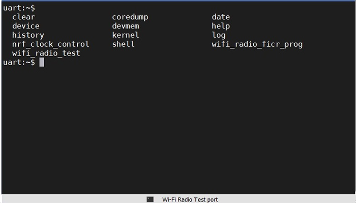
Wi-Fi Radio test port