Bluetooth: Peripheral UART
The Peripheral UART sample demonstrates how to use the Nordic UART Service (NUS). It uses the NUS service to send data back and forth between a UART connection and a Bluetooth® LE connection, emulating a serial port over Bluetooth LE.
Requirements
The sample supports the following development kits:
Hardware platforms |
PCA |
Board name |
|
|---|---|---|---|
PCA20053 |
|
||
nRF54LV10 DK |
PCA10188 |
|
|
nRF54LS05 DK |
PCA10214 |
nrf54ls05dk |
|
PCA10184 |
|
||
nRF54LC10 DK |
PCA10226 |
nrf54lc10dk |
|
PCA10156 |
|
||
PCA10156 |
|
||
PCA10156 |
|
||
PCA10175 |
|
||
PCA10095 |
|
||
PCA10040 |
|
||
PCA10056 |
|
||
PCA10100 |
|
||
PCA10100 |
|
||
PCA10112 |
|
For more security, it is recommended to use the */ns variant of the board target.
When built for this variant, the sample is configured to compile and run as a non-secure application using security by separation.
Therefore, it automatically includes Trusted Firmware-M that prepares the required peripherals and secure services to be available for the application.
Note
The boards
nrf52dk/nrf52810,nrf52840dk/nrf52811, andnrf52833dk/nrf52820only support the Minimal sample variant.When used with Thingy:53, the sample supports the MCUboot bootloader with serial recovery and SMP DFU over Bluetooth. Thingy:53 has no built-in SEGGER chip, so the UART 0 peripheral is not gated to a USB CDC virtual serial port.
When used with nRF5340 DK, the sample might support the MCUboot bootloader with serial recovery of the networking core image.
The sample also requires using a compatible application for Testing. You can use the Bluetooth Low Energy app for desktop or the nRF Connect for Mobile (or other similar applications, such as nRF Blinky or nRF Toolbox). Using mobile applications for testing requires a smartphone or tablet.
You can also test the application with the Bluetooth: Central UART sample. See the documentation for that sample for detailed instructions.
Note
If you build this application for Thingy:53, it enables additional features. See Application guide for Thingy:53 for details.
The sample also enables an additional USB CDC ACM class serial port that is used instead of UART 0. Because of that, it uses a separate USB Vendor and Product ID.
Overview
When connected, the sample forwards any data received on the RX pin of the UART 0 peripheral to the Bluetooth LE unit. On Nordic Semiconductor’s development kits, the UART 0 peripheral is typically gated through the SEGGER chip to a USB CDC virtual serial port.
Any data sent from the Bluetooth LE unit is sent out of the UART 0 peripheral’s TX pin.
Note
Thingy:53 uses the second instance of USB CDC ACM class instead of UART 0, because it has no built-in SEGGER chip that could be used to gate UART 0.
Debugging
In this sample, the UART console is used to send and read data over the NUS service. Debug messages are not displayed in this UART console. Instead, they are printed by the RTT logger.
If you want to view the debug messages, follow the procedure in Testing and optimization.
Note
On the Thingy:53, debug logs are provided over the USB CDC ACM class serial port instead of RTT or other logging backends.
For more information about debugging in the nRF Connect SDK, see Debugging an application.
FEM support
You can add support for the nRF21540 front-end module to this sample by using one of the following options, depending on your hardware:
Build the sample for one board that contains the nRF21540 FEM, such as nRF21540 DK.
Manually create a devicetree overlay file that describes how the nRF21540 FEM is connected to the SoC. See Configuring devicetree for different ways of adding the overlay file.
Provide nRF21540 FEM capabilities by using a shield, for example the nRF21540 EK shield that is available in the nRF Connect SDK. In this case, build the project for a board connected to the shield you are using with an appropriate variable included in the build command, for example
-DSHIELD=nrf21540ek. This variable instructs the build system to append the appropriate devicetree overlay file.To build the sample in nRF Connect for VS Code for an nRF52840 DK with the nRF21540 EK attached, add the shield variable in the build configuration’s Extra CMake arguments and rebuild the build configuration. For example:
-DSHIELD=nrf21540ek.See How to work with build configurations in the nRF Connect for VS Code documentation for more information.
To build the sample from the command line for an nRF52840 DK with the nRF21540 EK attached, use the following command within the sample directory:
west build -b nrf52840dk/nrf52840 -- -DSHIELD=nrf21540ekSee Programming nRF21540 EK for information about how to program when you are using a board with a network core, for example the nRF5340 DK.
Each of these options adds the description of the nRF21540 FEM to the devicetree. See Developing with Front-End Modules for more information about FEM in the nRF Connect SDK.
To add support for other front-end modules, add the respective devicetree file entries to the board devicetree file or the devicetree overlay file.
Minimal sample variant
You can build the sample with a minimum configuration as a demonstration of how to reduce code size and RAM usage. This variant is available for resource-constrained boards.
See Activating sample extensions for details.
USB CDC ACM extension
For the boards with the USB device peripheral, you can build the sample with support for the USB CDC ACM class serial port instead of the physical UART.
This build uses the sample-specific UART async adapter module that acts as a bridge between USB CDC ACM and Zephyr’s UART asynchronous API used by the sample.
See Activating sample extensions for details about how to build the sample with this extension using the prj_cdc.conf file.
Async adapter experimental module
The default sample configuration uses the UART async API. The sample uses the UART async adapter library to communicate with the USB CDC ACM driver. This is needed because the USB CDC ACM implementation provides only the interrupt interface.
To use the library, set the CONFIG_UART_ASYNC_ADAPTER Kconfig option to y.
MCUboot with serial recovery of the networking core image
For the nrf5340dk/nrf5340/cpuapp, it is possible to enable serial recovery of the network core while multi-image update is not enabled in the MCUboot.
See Activating sample extensions for details on how to build the sample with this feature using the nrf5340dk_app_sr_net.conf and nrf5340dk_mcuboot_sr_net.conf files.
User interface
The user interface of the sample depends on the hardware platform you are using.
- LED 1:
Blinks, toggling on/off every second, when the main loop is running and the device is advertising.
- LED 2:
Lit when connected.
- Button 1:
Confirm the passkey value that is printed in the debug logs to pair/bond with the other device.
- Button 2:
Reject the passkey value that is printed in the debug logs to prevent pairing/bonding with the other device.
- LED 0:
Blinks, toggling on/off every second, when the main loop is running and the device is advertising.
- LED 1:
Lit when connected.
- Button 0:
Confirm the passkey value that is printed in the debug logs to pair/bond with the other device.
- Button 1:
Reject the passkey value that is printed in the debug logs to prevent pairing/bonding with the other device.
- RGB LED:
The RGB LED channels are used independently to display the following information:
Red channel blinks with a period of two seconds, duty cycle 50%, when the main loop is running (device is advertising).
Green channel displays if device is connected.
- Button:
Confirm the passkey value that is printed in the debug logs to pair/bond with the other device. Thingy:53 has only one button, therefore the passkey value cannot be rejected by pressing a button.
Configuration
See Configuring and building for information about how to permanently or temporarily change the configuration.
Configuration options
The following sample-specific Kconfig options are used in this sample (located in samples/bluetooth/peripheral_uart/Kconfig) :
- CONFIG_BT_NUS_THREAD_STACK_SIZE
(int) Thread stack size
Stack size used in each of the two threads
- CONFIG_BT_NUS_UART_BUFFER_SIZE
(int) UART payload buffer element size
Size of the payload buffer in each RX and TX FIFO element
- CONFIG_BT_NUS_SECURITY_ENABLED
(bool) Security
Enable Bluetooth LE security for the UART service
- CONFIG_BT_NUS_UART_RX_WAIT_TIME
(int) Timeout for UART RX complete event
Wait for RX complete event time in microseconds
- CONFIG_SETTINGS
(unknown)
- CONFIG_ZMS
(unknown)
- CONFIG_NVS
(unknown)
Building and running
This sample can be found under samples/bluetooth/peripheral_uart in the nRF Connect SDK folder structure.
For more security, it is recommended to use the */ns variant of the board target (see the Requirements section above.)
When built for this variant, the sample is configured to compile and run as a non-secure application using security by separation.
Therefore, it automatically includes Trusted Firmware-M that prepares the required peripherals and secure services to be available for the application.
To build the sample, follow the instructions in Building an application for your preferred building environment. See also Programming an application for programming steps and Testing and optimization for general information about testing and debugging in the nRF Connect SDK.
Note
When building repository applications in the SDK repositories, building with sysbuild is enabled by default.
If you work with out-of-tree freestanding applications, you need to manually pass the --sysbuild parameter to every build command or configure west to always use it.
When building this sample with Sysbuild for an SoC that has a network core, the IPC radio firmware is automatically applied to the build.
The IPC radio is one of the companion components in the nRF Connect SDK and allows to use the radio peripheral from another core in a multicore device.
If needed, you can modify the IPC radio configuration in the prj.conf source file in the sample’s sysbuild/ipc_radio directory.
Experimental nRF54H20 SoC radio core only build
The sample can also be built in a configuration that allows it to run on the nRF54H20 SoC radio core only. To build the sample with this configuration, use the following command:
west build -b nrf54h20dk/nrf54h20/cpurad
Experimental Bluetooth Low Energy Remote Procedure Call interface
To build the sample with a Bluetooth Low Energy Remote Procedure Call interface, use the following command:
west build samples/bluetooth/peripheral_uart -b board_name --sysbuild -S nordic-bt-rpc -- -DFILE_SUFFIX=bt_rpc
Activating sample extensions
To activate the optional extensions supported by this sample, set EXTRA_CONF_FILE using the respective CMake option in the following manner:
For the minimal build variant, set it to
prj_minimal.conf.For the USB CDC ACM extension, set it to
prj_cdc.conf. Additionally, you need to set DTC_OVERLAY_FILE to theusb.overlayfile.For the MCUboot with serial recovery of the networking core image feature, set it to
nrf5340dk_app_sr_net.conf. You also need to set the mcuboot_EXTRA_CONF_FILE variant to thenrf5340dk_mcuboot_sr_net.conffile.
For more information about configuration files in the nRF Connect SDK, see Build and configuration system.
Testing
After programming the sample to your development kit, complete the following steps to test the basic functionality:
Connect the device to the computer to access UART 0. If you use a development kit, UART 0 is forwarded as a serial port. Serial ports are referred to as COM ports on Windows, /dev/ttyACM devices on Linux, and /dev/tty devices on macOS. To list Nordic Semiconductor devices connected to your computer together with their serial ports, open a terminal and run the
nrfutil device listcommand. Alternatively, check your operating system’s device manager or its equivalent. If you use Thingy:53, you must attach the debug board and connect an external USB to UART converter to it.Connect to the kit with a terminal emulator (for example, the Serial Terminal app). See Testing and optimization for the required settings and steps.
Reset the kit.
Observe that LED 1 is blinking and the device is advertising under the default name Nordic_UART_Service. You can configure this name using the
CONFIG_BT_DEVICE_NAMEKconfig option.Observe that the text “Starting Nordic UART service sample” is printed on the COM listener running on the computer.
Note
The nRF54 DKs use a different numbering pattern for LED and buttons. See the User interface section for full overview.
Connect the device to the computer to access UART 0. If you use a development kit, UART 0 is forwarded as a serial port. Serial ports are referred to as COM ports on Windows, /dev/ttyACM devices on Linux, and /dev/tty devices on macOS. To list Nordic Semiconductor devices connected to your computer together with their serial ports, open a terminal and run the
nrfutil device listcommand. Alternatively, check your operating system’s device manager or its equivalent. If you use Thingy:53, you must attach the debug board and connect an external USB to UART converter.Connect to the kit with a terminal emulator (for example, the Serial Terminal app). See Testing and optimization for the required settings and steps.
Reset the kit.
Observe that LED 0 is blinking and the device is advertising under the default name Nordic_UART_Service. You can configure this name using the
CONFIG_BT_DEVICE_NAMEKconfig option.Observe that the text “Starting Nordic UART service sample” is printed on the COM listener running on the computer.
Testing with nRF Connect for Mobile
You can test the sample pairing with a mobile device. For this purpose, use nRF Connect for Mobile (or other similar applications, such as nRF Blinky or nRF Toolbox).
To perform the test, complete the following steps:
Connect the device to the computer to access UART 0. If you use a development kit, UART 0 is forwarded as a serial port. Serial ports are referred to as COM ports on Windows, /dev/ttyACM devices on Linux, and /dev/tty devices on macOS. To list Nordic Semiconductor devices connected to your computer together with their serial ports, open a terminal and run the
nrfutil device listcommand. Alternatively, check your operating system’s device manager or its equivalent. If you use Thingy:53, you must attach the debug board and connect an external USB to UART converter.Connect to the kit with a terminal emulator (for example, the Serial Terminal app). See Testing and optimization for the required settings and steps.
Optionally, you can display debug messages. See Debugging for details.
Install and start the nRF Connect for Mobile application on your Android device.
If the application does not automatically start scanning, tap the Play icon in the upper right corner.
Connect to the device using nRF Connect for Mobile.
Observe that LED 2 is lit.
Optionally, pair or bond with the device with MITM protection. This requires using the passkey value displayed in debug messages.
See Configuration options for details on how to enable the MITM protection.
See Debugging for details on how to access debug messages containing passkey.
To confirm pairing or bonding, press Button 1 on the device and accept the passkey value on the smartphone.
In the application, observe that the services are shown in the connected device.
Select Nordic UART Service and tap the up arrow button for the UART RX characteristic. A pop-up window with a text input field appears. You can write to the UART RX and get the text displayed on the COM listener.
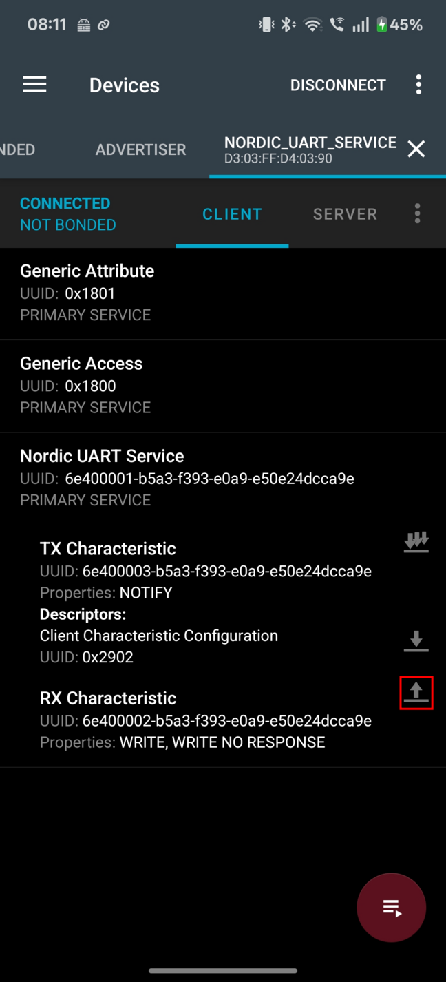
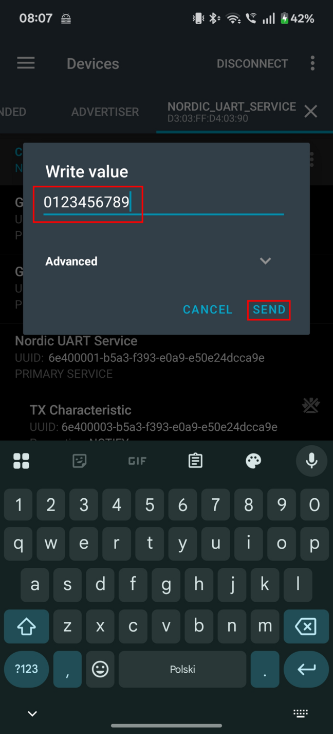
Type “0123456789” and tap SEND.
Verify that the text “0123456789” is displayed on the COM listener.
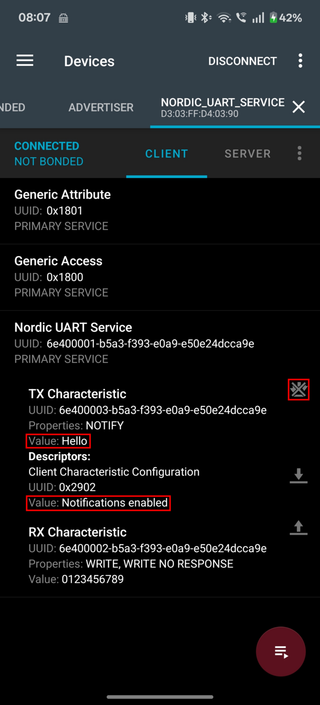
To send data from the device to your phone or tablet, in the terminal emulator connected to the sample, enter any text, for example, “Hello”, and press Enter to see it on the COM listener.
The text is sent through the development kit to your mobile device over a Bluetooth LE link. It appears in the Value field of UART TX characteristic.
If the text does not appear, check if notifications are enabled for this characteristic. You can toggle the notification settings with a button in the upper right corner of UART TX Characteristic.
On your Android device, tap the three-dot menu next to Disconnect and select Show log.
The device displays the text in the nRF Connect for Mobile log.
Disconnect the device in nRF Connect for Mobile.
Observe that LED 2 turns off.
Connect the device to the computer to access UART 0. If you use a development kit, UART 0 is forwarded as a serial port. Serial ports are referred to as COM ports on Windows, /dev/ttyACM devices on Linux, and /dev/tty devices on macOS. To list Nordic Semiconductor devices connected to your computer together with their serial ports, open a terminal and run the
nrfutil device listcommand. Alternatively, check your operating system’s device manager or its equivalent. If you use Thingy:53, you must attach the debug board and connect an external USB to UART converter.Connect to the kit with a terminal emulator (for example, the Serial Terminal app). See Testing and optimization for the required settings and steps.
Optionally, you can display debug messages. See Debugging for details.
Install and start the nRF Connect for Mobile application on your iOS device.
If the application does not automatically start scanning, tap the Play icon in the upper right corner.
Connect to the device using nRF Connect for Mobile.
Observe that LED 2 is lit.
Optionally, pair or bond with the device with MITM protection. This requires using the passkey value displayed in debug messages.
See Configuration options for details on how to enable the MITM protection.
See Debugging for details on how to access debug messages containing passkey.
To confirm pairing or bonding, press Button 1 on the device and accept the passkey value on the smartphone.
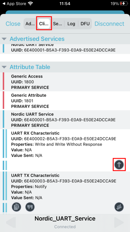
In the application, change to Client tab and observe that the services are shown in the connected device.
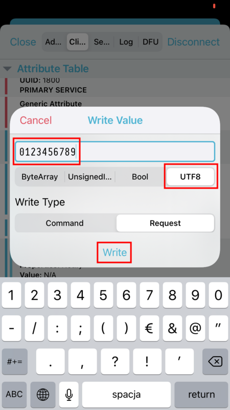
In Nordic UART Service, tap the up arrow button for the UART RX characteristic. A Write Value pop-up window with a text input field appears. You can write to the UART RX and get the text displayed on the COM listener.
Type “0123456789”, select “UTF8” input type and tap Write.
Verify that the text “0123456789” is displayed on the COM listener.
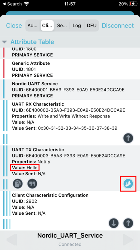
To send data from the device to your phone or tablet, in the terminal emulator connected to the sample, enter any text, for example, “Hello”, and press Enter to see it on the COM listener.
The text is sent through the development kit to your mobile device over a Bluetooth LE link. It appears in the Value field of UART TX characteristic.
If the text does not appear, check if notifications are enabled for this characteristic. You can toggle the notification settings with a button in the lower right corner of UART TX Characteristic.
On your iOS device, select the Log tab.
The device displays the text in the nRF Connect for Mobile log.
Disconnect the device in nRF Connect for Mobile.
Observe that LED 2 turns off.
Note
The nRF54 DKs use a different numbering pattern for LED and buttons. See the User interface section for full overview.
Connect the device to the computer to access UART 0. If you use a development kit, UART 0 is forwarded as a serial port. Serial ports are referred to as COM ports on Windows, /dev/ttyACM devices on Linux, and /dev/tty devices on macOS. To list Nordic Semiconductor devices connected to your computer together with their serial ports, open a terminal and run the
nrfutil device listcommand. Alternatively, check your operating system’s device manager or its equivalent. If you use Thingy:53, you must attach the debug board and connect an external USB to UART converter.Connect to the kit with a terminal emulator (for example, the Serial Terminal app). See Testing and optimization for the required settings and steps.
Optionally, you can display debug messages. See Debugging for details.
Install and start the nRF Connect for Mobile application on your Android device.
If the application does not automatically start scanning, tap the Play icon in the upper right corner.
Connect to the device using nRF Connect for Mobile.
Observe that LED 1 is lit.
Optionally, pair or bond with the device with MITM protection. This requires using the passkey value displayed in debug messages.
See Configuration options for details on how to enable the MITM protection.
See Debugging for details on how to access debug messages containing passkey.
To confirm pairing or bonding, press Button 0 on the device and accept the passkey value on the smartphone.
In the application, observe that the services are shown in the connected device.
Select Nordic UART Service and tap the up arrow button for the UART RX characteristic. A pop-up window with a text input field appears. You can write to the UART RX and get the text displayed on the COM listener.
Type “0123456789” and tap SEND.
Verify that the text “0123456789” is displayed on the COM listener.
To send data from the device to your phone or tablet, in the terminal emulator connected to the sample, enter any text, for example, “Hello”, and press Enter to see it on the COM listener.
The text is sent through the development kit to your mobile device over a Bluetooth LE link. It appears in the Value field of UART TX characteristic.
If the text does not appear, check if notifications are enabled for this characteristic. You can toggle the notification settings with a button in the upper right corner of UART TX Characteristic.
On your Android device, tap the three-dot menu next to Disconnect and select Show log.
The device displays the text in the nRF Connect for Mobile log.
Disconnect the device in nRF Connect for Mobile.
Observe that LED 1 turns off.
Connect the device to the computer to access UART 0. If you use a development kit, UART 0 is forwarded as a serial port. Serial ports are referred to as COM ports on Windows, /dev/ttyACM devices on Linux, and /dev/tty devices on macOS. To list Nordic Semiconductor devices connected to your computer together with their serial ports, open a terminal and run the
nrfutil device listcommand. Alternatively, check your operating system’s device manager or its equivalent. If you use Thingy:53, you must attach the debug board and connect an external USB to UART converter.Connect to the kit with a terminal emulator (for example, the Serial Terminal app). See Testing and optimization for the required settings and steps.
Optionally, you can display debug messages. See Debugging for details.
Install and start the nRF Connect for Mobile application on your iOS device.
If the application does not automatically start scanning, tap the Play icon in the upper right corner.
Connect to the device using nRF Connect for Mobile.
Observe that LED 1 is lit.
Optionally, pair or bond with the device with MITM protection. This requires using the passkey value displayed in debug messages.
See Configuration options for details on how to enable the MITM protection.
See Debugging for details on how to access debug messages containing passkey.
To confirm pairing or bonding, press Button 0 on the device and accept the passkey value on the smartphone.
In the application, change to Client tab and observe that the services are shown in the connected device.
In Nordic UART Service, tap the up arrow button for the UART RX characteristic. A Write Value pop-up window with a text input field appears. You can write to the UART RX and get the text displayed on the COM listener.
Type “0123456789”, select “UTF8” input type and tap Write.
Verify that the text “0123456789” is displayed on the COM listener.
To send data from the device to your phone or tablet, in the terminal emulator connected to the sample, enter any text, for example, “Hello”, and press Enter to see it on the COM listener.
The text is sent through the development kit to your mobile device over a Bluetooth LE link. It appears in the Value field of UART TX characteristic.
If the text does not appear, check if notifications are enabled for this characteristic. You can toggle the notification settings with a button in the lower right corner of UART TX Characteristic.
On your iOS device, select the Log tab.
The device displays the text in the nRF Connect for Mobile log.
Disconnect the device in nRF Connect for Mobile.
Observe that LED 1 turns off.
Testing with Bluetooth Low Energy app
If you have an nRF52 Series DK with the Peripheral UART sample and either a dongle or second Nordic Semiconductor development kit that supports the Bluetooth Low Energy app, you can test the sample on your computer. Use the Bluetooth Low Energy app in nRF Connect for Desktop for testing.
To perform the test, complete the following steps:
Install the Bluetooth Low Energy app in nRF Connect for Desktop.
Connect to your nRF52 Series DK.
Connect the dongle or second development kit to a USB port of your computer.
Open the app.
Select the serial port that corresponds to the dongle or the second development kit. Do not select the kit you want to test just yet.
Note
If the dongle or the second development kit has not been used with the Bluetooth Low Energy app before, you may be asked to update the J-Link firmware and connectivity firmware on the nRF SoC to continue. When the nRF SoC has been updated with the correct firmware, the app finishes connecting to your device over USB. When the connection is established, the device appears in the main view.
Click Start scan.
Find the development kit you want to test and click the corresponding Connect button.
The default name for the Peripheral UART sample is Nordic_UART_Service.
Select the Universal Asynchronous Receiver/Transmitter (UART) RX characteristic value.
Write
30 31 32 33 34 35 36 37 38 39(the hexadecimal value for the string “0123456789”) and click Write.The data is transmitted over Bluetooth LE from the app to the DK that runs the Peripheral UART sample. The terminal emulator connected to the development kit then displays
"0123456789".In the terminal emulator, enter any text, for example
Hello.The data is transmitted to the development kit that runs the Peripheral UART sample. The UART TX characteristic displayed in the app changes to the corresponding ASCII value. For example, the value for
Hellois48 65 6C 6C 6F.
Dependencies
This sample uses the following nRF Connect SDK libraries:
In addition, it uses the following Zephyr libraries:
include/zephyr/types.hboards/arm/nrf*/board.h-
include/kernel.h
-
include/gpio.hinclude/uart.h
API:
include/bluetooth/bluetooth.hinclude/bluetooth/gatt.hinclude/bluetooth/hci.hinclude/bluetooth/uuid.h
The sample also uses the following secure firmware component: