Wi-Fi: Throughput
The Throughput sample provides a framework for users to measure the achievable IP networking throughput of applications using Nordic Semiconductor’s Wi-Fi® chipsets.
Requirements
The sample supports the following development kit:
Hardware platforms |
PCA |
Board name |
Shields |
|
|---|---|---|---|---|
PCA10143 |
|
|||
PCA10184 |
|
|
||
PCA10175 |
|
|
Overview
The sample demonstrates how to measure the network throughput of a Nordic Wi-Fi-enabled platform using the zperf sample application under the different Wi-Fi stack configuration profiles. The sample requires additional software, such as the Wi-Fi iperf application. When the sample runs Wi-Fi UDP/TCP throughput in client mode, a peer device runs UDP/TCP throughput in server mode. When the sample runs Wi-Fi UDP/TCP throughput in server mode, a peer device runs UDP/TCP throughput in client mode.
See Usage profiles for different Wi-Fi stack configuration profiles. See Network Traffic Generator for instructions on how to use zperf and iperf applications.
Test setup
The following figure shows a reference test setup.
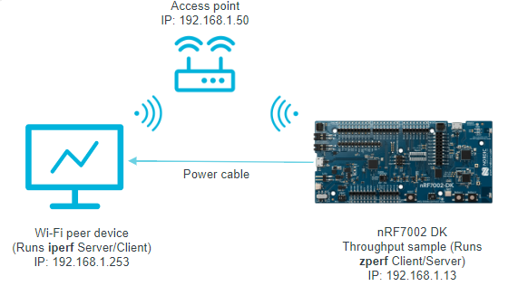
Wi-Fi Throughput sample test setup
The reference test setup shows the connections between the following devices:
The nRF7002 DK on which the throughput sample runs the zperf application.
Wi-Fi peer device that runs the iperf application.
Building and running
This sample can be found under samples/wifi/throughput in the nRF Connect SDK folder structure.
For more security, it is recommended to use the */ns variant of the board target (see the Requirements section above.)
When built for this variant, the sample is configured to compile and run as a non-secure application using security by separation.
Therefore, it automatically includes Trusted Firmware-M that prepares the required peripherals and secure services to be available for the application.
To build the sample, follow the instructions in Building an application for your preferred building environment. See also Programming an application for programming steps and Testing and optimization for general information about testing and debugging in the nRF Connect SDK.
Note
When building repository applications in the SDK repositories, building with sysbuild is enabled by default.
If you work with out-of-tree freestanding applications, you need to manually pass the --sysbuild parameter to every build command or configure west to always use it.
Note
The sample is supported on the nRF7002 DK with QSPI as the interface between the nRF5340 host and the nRF7002 device.
To build for the nRF7002 DK, use the nrf7002dk/nrf5340/cpuapp board target.
The following is an example of the CLI command:
west build -b nrf7002dk/nrf5340/cpuapp
To build for the nRF7002 DK with different profiles for Station mode, use the following CLI commands:
To build for the nRF7002 DK, with the IoT device profile for Station mode, use the iot-devices overlay configuration.
west build -p -b nrf7002dk/nrf5340/cpuapp -- -DEXTRA_CONF_FILE=overlay-iot-devices.conf
To build for the nRF7002 DK, with the memory-optimized profile for Station mode, use the memory-optimized overlay configuration.
west build -p -b nrf7002dk/nrf5340/cpuapp -- -DEXTRA_CONF_FILE=overlay-memory-optimized.conf
To build for the nRF7002 DK, with the high performance profile for Station mode, use the high-performance overlay configuration.
west build -p -b nrf7002dk/nrf5340/cpuapp -- -DEXTRA_CONF_FILE=overlay-high-performance.conf
To build for the nRF7002 DK, with the TX prioritized profile for Station mode, use the tx-prio overlay configuration.
west build -p -b nrf7002dk/nrf5340/cpuapp -- -DEXTRA_CONF_FILE=overlay-tx-prio.conf
To build for the nRF7002 DK, with the RX prioritized profile for Station mode, use the rx-prio overlay configuration.
west build -p -b nrf7002dk/nrf5340/cpuapp -- -DEXTRA_CONF_FILE=overlay-rx-prio.conf
Refer to the sample.yaml file for a complete list of supported boards and their corresponding build command options.
Supported CLI commands
zperf is the command line tool and supports the following UART CLI subcommands:
Subcommands |
Description |
|---|---|
connectap |
Connect to AP
|
setip |
Set IP address
<my ip> <prefix len>
Example - setip 2001:db8::2 64
Example - setip 192.0.2.2
|
tcp |
Upload/Download TCP data
|
udp |
Upload/Download UDP data
|
version |
zperf version
|
The following is an example of the zperf command:
zperf <udp/tcp> <upload/download> <dest ip> [<dest port> <duration> <packet size>[K] <baud rate>[K|M]]
Testing
After programming the sample to your development kit, complete the following steps to test it:
Connect the kit to the computer using a USB cable. The kit is assigned a serial port. Serial ports are referred to as COM ports on Windows, /dev/ttyACM devices on Linux, and /dev/tty devices on macOS. To list Nordic Semiconductor devices connected to your computer together with their serial ports, open a terminal and run the
nrfutil device listcommand. Alternatively, check your operating system’s device manager or its equivalent.Connect to the kit with a terminal emulator (for example, the Serial Terminal app). See Testing and optimization for the required settings and steps.
Scan for the Wi-Fi networks in range using the following command:
wifi scanThe output should be similar to the following:
Scan requested

Num  | SSID                             (len) | Chan (Band)   | RSSI | Security        | BSSID             | MFP
1    | abcd                             8     | 11   (2.4GHz) | -18  | WPA2-PSK        | xx:xx:xx:xx:xx:xx | Disable
2    | efgh                             7     | 40   (5GHz  ) | -21  | OPEN            | xx:xx:xx:xx:xx:xx | Disable
3    | mnopq                            8     | 6    (2.4GHz) | -29  | OPEN            | xx:xx:xx:xx:xx:xx | Disable
6    | stuvwx                           24    | 11   (2.4GHz) | -47  | WPA3-SAE        | xx:xx:xx:xx:xx:xx | Required
Connect to your preferred network using the following command:
wifi connect -s <SSID> -k <key_management> -p <passphrase><SSID>is the SSID of the network you want to connect to, and<passphrase>is its passphrase.Check the connection status after 30 seconds, using the following command:
wifi statusIf the connection is established, you should see an output similar to the following:
Status: successful
==================
State: COMPLETED
Interface Mode: STATION
Link Mode: WIFI 4 (802.11n/HT)
SSID: xxxxx
BSSID: xx:xx:xx:xx:xx:xx
Band: 2.4GHz
Channel: 11
Security: WPA2-PSK
MFP: Optional
RSSI: -28
Beacon Interval: 100
DTIM: 1
TWT: Not supported
Initiate a ping and verify data connectivity using the following commands:
net ping <resolved hostname>See the following example:
net ping 192.168.1.1
PING 192.168.1.1
28 bytes from 192.168.1.1 to 192.168.1.1: icmp_seq=1 ttl=64 time=0 ms
28 bytes from 192.168.1.1 to 192.168.1.1: icmp_seq=2 ttl=64 time=0 ms
28 bytes from 192.168.1.1 to 192.168.1.1: icmp_seq=3 ttl=64 time=0 ms
Run the
iperfcommands (TX) on the peer device and thezperfcommands (RX) on the sample as shown in the following table.Traffic type
TX (Peer device)
RX (Sample)
UDP
iperf -s -i 1 -u
zperf udp upload <dest ip> <dest port> <duration> <packet size> <baud rate>
TCP
iperf -s -i 1
zperf tcp upload <dest ip> <dest port> <duration> <packet size> <baud rate>
The sample shows the following output (
zperfTX):$ zperf udp upload 192.168.1.253 5001 10 1K 50M Remote port is 5001 Invalid IPv6 address 192.168.1.253 Connecting to 192.168.1.253 Duration: 10.00 s Packet size: 1024 bytes Rate: 51200 kbps Starting... Rate: 50.00 Mbps Packet duration 156 us - Upload completed! LAST PACKET NOT RECEIVED!!! Statistics: server (client) Duration: 29.45 m (10.00 s) Num packets: 0 (37440) Num packets out order: 25711 Num packets lost: 4657 Jitter: 51.33 m Rate: 0 Kbps (29.24 Mbps)
Run the
iperfcommands (RX) on the peer device and thezperfcommands (TX) on the sample as shown in the following table.Traffic type
TX (Sample)
RX (Peer device)
UDP
zperf udp download <dest port>
iperf -c <ipaddress> -i 1 -t <duration> -u -b <baud rate>
TCP
zperf tcp download <dest port>
iperf -c <ipaddress> -i 1 -t <duration> -b <baud rate>
The sample shows the following output:
$ zperf udp download 5001
UDP server started on port 5001
<inf> net_zperf: Binding to 192.168.1.13
<inf> net_zperf: Binding to ::
<inf> net_zperf: Listening on port 5001
New session started.
End of session!
duration:              10.02 s
received packets:      10694
nb packets lost:       33884
nb packets outorder:   0
jitter:                        5.20 ms
rate:                  11.96 Mbps
Stop the
zperfUDP/TCP download using the following command:zperf <udp/tcp> download stopThe sample shows the following output:
$ zperf udp download stop
UDP server stopped
Results
The following table collects a summary of results obtained when throughput tests are run for different profiles.
Profile |
UDP TX |
UDP RX |
TCP TX |
TCP RX |
|---|---|---|---|---|
IoT devices |
6.3 Mbps |
22.9 Mbps |
8.3 Mbps |
6.5 Mbps |
Memory-optimized |
6.3 Mbps |
23.6 Mbps |
6 Mbps |
8.1 Mbps |
High performance |
16.4 Mbps |
22.5 Mbps |
11.2 Mbps |
12.1 Mbps |
TX prioritized |
17.8 Mbps |
21.1 Mbps |
9.5 Mbps |
8.1 Mbps |
RX prioritized |
9.3 Mbps |
23.5 Mbps |
7.4 Mbps |
8.9 Mbps |
Note
As shown in the table above, the measured throughputs are based on tests conducted using the nRF7002 DK. The results represent the best throughput, averaged over three iterations, and were obtained with a good RSSI signal in a clean environment(RF Chamber).
Dependencies
This sample uses the following library:
This sample also uses modules found in the following locations in the nRF Connect SDK folder structure:
modules/lib/hostapmodules/mbedtls