

TF-M memory partitioning
As the Secure Processing Environment (SPE), TF-M is the first image to run after the bootloader. It is therefore responsible for setting up the hardware-enforced isolation between the secure and non-secure worlds before it hands over execution to the non-secure application. This page explains where the partition boundaries come from, how they are organized, and how they are turned into a security policy in hardware.
TF-M and devicetree partitioning overview
TF-M partitioning involves two related concepts: a devicetree memory region (also called a devicetree partition) is an address range declared in devicetree, and a TF-M partition is a secure-image component placed inside one of those regions.
Devicetree memory regions in the non-secure image and in storage areas set the security attributes of flash and RAM.
TF-M partitions in the secure image (also known as secure partitions) implement secure services and store secure data. They are isolated from the non-secure application code.
When you build TF-M, the nRF Connect SDK build system defines the devicetree memory regions using Zephyr’s devicetree-based partitioning. It then calls the TF-M Build System to create TF-M partitions within the secure devicetree memory regions. In TF-M, this second step is performed by Secure Partition Manager (SPM).
The following diagram shows a simplified view of the partitioning process:
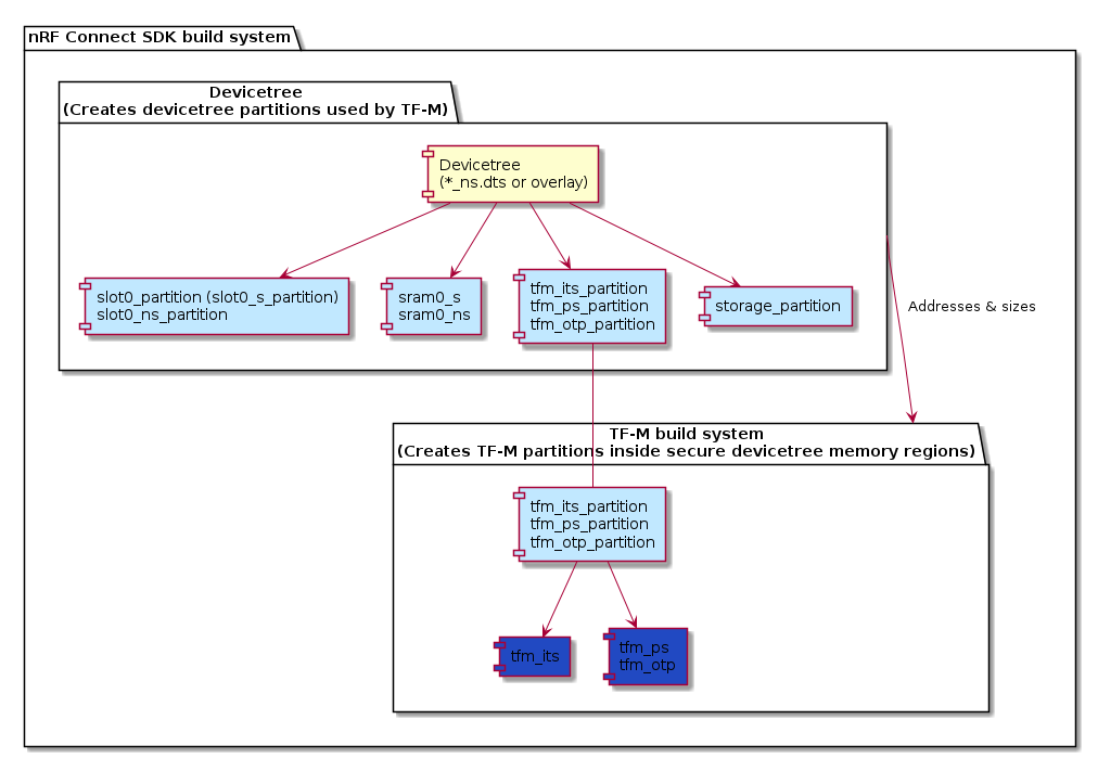
See the following sections for more information.
Devicetree memory regions and TF-M partitions
With devicetree-based partitioning, the memory region nodes in the board’s *_ns.dts files (or in a devicetree overlay) are the single source of truth for the memory map.
At build time, the TF-M build system reads the addresses and sizes of these nodes and uses them to place the images and to program the memory protection hardware.
Devicetree memory regions used for TF-M
The following table lists the devicetree memory regions used for TF-M partitions:
Devicetree memory region (node) |
Purpose |
Additional information |
|---|---|---|
|
Memory region for the secure image (SPE); defines the secure code start address and size. |
This is |
|
Memory region for the non-secure image (NSPE). |
Its start address is the boundary between the secure and non-secure worlds in non-volatile memory. The |
|
Memory region for the secure RAM. |
|
|
Memory region for the non-secure RAM. |
|
|
Memory region for the non-secure storage area. |
Used when non-secure storage is enabled. |
What marks a region as secure or non-secure
During its startup, TF-M uses the memory region addresses from devicetree to give each flash and RAM region a Secure or Non-secure attribute:
Devicetree memory region (node) |
Security attribute at startup |
|---|---|
slot0_partition or slot0_s_partitionsram0_s |
Secure |
slot0_ns_partitionsram0_nsstorage_partition |
Non-secure |
|
Non-secure when MCUboot DFU is configured.
The secondary slot stages the downloaded update image, even though the update includes the secure image.
The running secure world is only ever the validated image in the primary slot.
|
The attribution is enforced in hardware by the following peripherals, depending on the device family:
Device family |
Hardware peripheral that enforces the attribution |
|---|---|
nRF53 and nRF91 Series |
System Protection Unit (SPU) |
nRF54L Series |
Memory Protection Controller (MPC) and Security Attribution Unit (SAU)
See also TF-M partitioning limitations.
|
These peripherals can only switch the security attribute at fixed region boundaries, whose size is given by CONFIG_NRF_TRUSTZONE_FLASH_REGION_SIZE (flash) and CONFIG_NRF_TRUSTZONE_RAM_REGION_SIZE (RAM).
As a result, every boundary between a secure and a non-secure region must fall on a multiple of the region size.
See the following section for more information.
TF-M partitions in the secure memory regions
The memory regions in slot0_partition or slot0_s_partition define the size and placement of the following TF-M partitions:
Devicetree memory region (node) |
TF-M build system name |
Description |
|---|---|---|
|
|
TF-M partition for Protected Storage. |
|
|
TF-M partition for Internal Trusted Storage. |
|
|
TF-M partition for OTP/NV counters. |
The TF-M build system consumes the values of these nodes through generated devicetree macros, so changing a reg property in devicetree directly changes where TF-M places the corresponding region and how it configures the hardware.
Size of the TF-M partitions
The required size of the TF-M partitions in devicetree-based partitioning is affected by multiple configuration options and hardware-related options. The code and memory size of TF-M increases when more services are enabled, but the selected hardware also places limitations on how the separation of secure and non-secure is made.
TF-M is linked as a separate image that occupies its own flash and RAM partitions in the final binary. With devicetree-based partitioning, the reserved sizes of these partitions are taken directly from the devicetree:
The secure RAM size comes from the
sram0_snode.The secure code size comes either from
slot0_s_partitionorslot0_partition, with the following distinction:The
slot0_s_partitionnode when the secure image is a sub-partition of the combinedslot0_partition.The
slot0_partitionnode when there is no separate secure sub-partition.
TF-M memory region alignment requirements
TF-M requires that secure and non-secure region addresses and sizes are aligned to the flash region size specified by the CONFIG_NRF_TRUSTZONE_FLASH_REGION_SIZE Kconfig option.
The default board devicetree memory region layouts already comply with this requirement.
If you change the memory region layout in devicetree, you are responsible for keeping these region boundaries aligned.
Alignment requirements per device family
Given that the security policy is enforced by different hardware on different device families, the alignment requirements are different for each device family:
Device family |
Hardware peripheral |
|
|---|---|---|
nRF53 and nRF91 Series |
System Protection Unit (SPU) |
Represents the SPU flash region size. |
nRF54L15 |
Memory Protection Controller (MPC) |
Represents the MPC region size. |
The region sizes must match the RAM and ROM granularity of the device family’s hardware that enforces the security policy:
Family |
RAM granularity |
ROM granularity |
|---|---|---|
nRF91 Series |
8 kB |
32 kB |
nRF53 Series |
8 kB |
16 kB |
nRF54 Series |
4 kB |
4 kB |
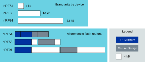
Partition alignment granularity on different nRF devices
The imaginary example above shows a worst-case scenario in the nRF91 Series where the flash region size is 32 kB and both the TF-M binary and secure storage are 12 kB. This leaves a significant amount of unused space in the flash region. In a real-world scenario, the size of the TF-M binary and secure storage is usually much larger.
When you define memory regions in devicetree-based partitioning, you solely are responsible for following the alignment requirements.
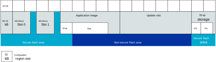
Example of aligning partitions with flash regions
Alignment requirements for devicetree partition sets
You need to align the following partitions:
Secure image (
slot0_partitionorslot0_s_partition)Non-secure image (
slot0_ns_partition)Secondary slot (
slot1_partition, when MCUboot DFU is configured)Storage memory regions (
tfm_ps_partition,tfm_its_partition, andtfm_otp_partition)Non-secure storage memory region (
storage_partition)
Both the start address and the size of these memory regions need to be aligned with the TrustZone flash region size through the CONFIG_NRF_TRUSTZONE_FLASH_REGION_SIZE Kconfig option.
You do not necessarily need to align each of the regions separately.
What actually has to be aligned is each boundary where the security attribute changes, not every region in isolation.
If there is a set of multiple consecutive regions and these regions share the same security attribute, you need to align only the start address and the end address of the entire set.
For example, the secure storage regions tfm_ps_partition, tfm_its_partition, and tfm_otp_partition are a set of consecutive devicetree partitions that are placed back-to-back inside the secure region, so only the start address of the first partition and the end address of the last partition in the contiguous block need to be aligned to the region size.
Note
The slot0_ns_partition is placed directly after the secure image, so the end address of the secure image is the same as the start address of slot0_ns_partition.
As a result, altering the size of the secure image shifts the start address of the non-secure image.
Alignment example
The following devicetree snippet shows a non-aligned configuration for the nRF54L15, which has a TrustZone flash region size CONFIG_NRF_TRUSTZONE_FLASH_REGION_SIZE of 0x1000.
&cpuapp_rram {
    partitions {
        slot0_partition: partition@0 {
            compatible = "zephyr,mapped-partition";
            label = "image-0";
            reg = <0x0 0x7f800>;
        };

        slot0_ns_partition: partition@7f800 {
            compatible = "zephyr,mapped-partition";
            label = "image-0-nonsecure";
            reg = <0x7f800 0xf4800>;
        };
    };
};
In the above example, the slot0_ns_partition starts at address 0x7f800, which is not aligned with the requirement of 0x1000.
Because slot0_ns_partition is placed directly after the secure image, you can fix the alignment by increasing the size of the secure image to the next multiple of the region size (0x80000).
This shifts the start address of slot0_ns_partition to an aligned address and reduces its size by the same amount, keeping the end address unchanged:
&cpuapp_rram {
    partitions {
        slot0_partition: partition@0 {
            compatible = "zephyr,mapped-partition";
            label = "image-0";
            reg = <0x0 0x80000>;
        };

        slot0_ns_partition: partition@80000 {
            compatible = "zephyr,mapped-partition";
            label = "image-0-nonsecure";
            reg = <0x80000 0xf4000>;
        };
    };
};
What happens if the devicetree layout is not aligned
Because the hardware attributes whole regions, a memory region boundary that is not aligned to the region size cannot be represented exactly. The hardware can only place the boundary on a multiple of the region size, so a misaligned secure-to-non-secure boundary is rounded down to the start of the region that contains it, and that whole region is marked Non-secure.
Caution
Because of the rounding down, the secure code or data that shares this region with the boundary becomes accessible to the non-secure application. This silently breaks the isolation that TF-M is meant to provide, rather than producing an obvious error.
Sharing a region also collides on access permissions, not only on the security attributes. On nRF53 and nRF91 Series devices, TF-M configures the non-secure image as readable, writable, and executable, but configures the non-secure storage region as readable and writable only (not executable), and it applies the storage configuration last. If the non-secure image and a storage region share an SPU region, that region ends up non-executable, so non-secure code located in it fails to execute. For this reason, you must keep all memory regions that border a security change aligned to the region size.
How to catch misaligned layouts at build time
The build system does not catch every misaligned layout, and how a misaligned boundary is reported depends on the device family and the build type:
Device family |
Debug builds |
Release builds |
|---|---|---|
nRF54L Series |
Programming the MPC triggers a runtime assertion: a misaligned partition is detected at boot. |
Misaligned devicetree layout is not reported (assertions are compiled out), which silently breaks the isolation. |
nRF53 and nRF91 Series |
The SPU silently rounds the boundary down, and only the misaligned secure-gateway region is guarded by assertions. |
Misaligned devicetree layout is not reported (assertions are compiled out), which silently breaks the isolation. |
To enable the debug build type with assertions, use the CONFIG_TFM_CMAKE_BUILD_TYPE_DEBUG Kconfig option (for example, by building with CONFIG_DEBUG_OPTIMIZATIONS.)
TF-M partitioning limitations
The following limitations apply to the TF-M partitioning on nRF54L Series devices that limit the number of switches between secure and non-secure regions:
The number of SAU regions is limited to four.
The number of MPC regions is limited among the nRF54L Series devices, and especially on nRF54L15 and nRF54L10.
These are hardware limitations and cannot be worked around.
Role of Secure Partition Manager
TF-M’s Secure Partition Manager (SPM) is a core module of TF-M that is responsible for configuring the secure and non-secure regions and their attributes. It is used by TF-M Core to configure the secure and non-secure memory regions and their attributes and initialize the secure and non-secure hardware peripherals.
For more information, see Secure Partition Manager (SPM) in the TF-M documentation.
The nRF Connect SDK lets you configure the SPM backend to use when you are configuring TF-M. The following table lists the available SPM backends and the isolation levels they support:
Backend |
Option |
Description |
Allowed isolation levels |
|---|---|---|---|
Secure Function (SFN) |
With SFN, the Secure Partition is made up of a collection of callback functions that implement secure services. |
Level 1 |
|
Inter-Process Communication (IPC) |
With IPC, each Secure Partition processes signals in any order, and can defer responding to a message while continuing to process other signals. |
Levels 1, 2 and 3 |
Configuring TF-M partitions for TF-M services
When you are configuring TF-M, you can configure the TF-M partitions for the TF-M services.
Each service is implemented as a separate TF-M partition, which provides the execution environment for the service. It handles secure function calls and ensures that the service’s code and data are protected from unauthorized access.
Following are the available Kconfig options for TF-M partitions:
Option name |
Description |
Default value |
Dependencies |
|---|---|---|---|
Provides Platform service. |
Enabled |
||
Provides Crypto service. |
Enabled |
||
Provides Protected Storage service. |
Enabled |
PLATFORM, CRYPTO |
|
Provides Internal Trusted Storage service. |
Enabled |
||
Provides Initial Attestation service. |
Disabled |
CRYPTO |
Sizing the Internal Trusted Storage
The storage for the Internal Trusted Storage service is a separate tfm_its partition.
The devicetree partitioning mechanism can only align the start address of the tfm_its partition with the flash region size (see TF-M memory region alignment requirements).
TF-M does not guarantee in build time that the tfm_its partition can hold the assets configured with the CONFIG_TFM_ITS_NUM_ASSETS and CONFIG_TFM_ITS_MAX_ASSET_SIZE options.
Depending on the available flash size, the ITS can use one or two flash pages (4 KB) for ensuring power failure safe operations.
In addition, ITS stores the bookkeeping information for the assets in the flash memory and the bookkeeping size scales with the configured number of assets.
This can leave a very small amount of space for the actual assets.
It is recommended to test the ITS with the intended assets to ensure they fit in the available space.
Sizing the Protected Storage partition
The storage for the Protected Storage service is a separate tfm_ps partition.
Additionally, the PS partition requires non-volatile counters for rollback protection.
Those are stored in the tfm_otp_nv_counters partition.
Similarly to Sizing the Internal Trusted Storage, the devicetree partitioning mechanism can only align the start addresses of the partitions with the flash region size.
TF-M does not guarantee in build time that the tfm_ps partition can hold the assets configured with the CONFIG_TFM_PS_NUM_ASSETS and CONFIG_TFM_PS_MAX_ASSET_SIZE options.
The PS partition uses the ITS internally to store the assets in tfm_ps.
This means that some of the flash space is reserved for the ITS functionality.
Additionally, the PS service stores the file metadata in object tables, which also consumes flash space.
The size of the object table scales with the number of configured assets and two object tables (old and new) are required when performing PS operations.
This might leave a very small amount of space for the actual assets.
It is highly recommended to test the PS with the intended assets to ensure they fit in the available space.
Custom and renamed partitions
You can add custom devicetree partitions and custom TF-M partitions to your application. The way they are recognized and handled by TF-M depends on whether they are correctly configured for use with TF-M.
Partitioning of custom and renamed devicetree partitions
TF-M resolves a fixed set of devicetree node labels (the name: in name: partition@...).
What happens to a custom or renamed devicetree partition depends on whether it is one of these labels known to TF-M.
Required node labels
The following node labels are required for a devicetree memory region to be recognized by TF-M. Renaming or removing them makes the secure image fail to build:
slot0_partition(orslot0_s_partitionwhen the secure image is a sub-partition of a combined MCUboot slot) - Secure code.slot0_ns_partition- Non-secure code.sram0_sandsram0_ns- Secure and non-secure RAM.
Optional node labels
The following node labels are optional and are only used when present:
slot1_partition(orslot1_ns_partitionon TrustZone targets, where MCUboot uses the_nssuffix) - Secondary (upgrade) slot.tfm_ps_partition,tfm_its_partition,tfm_otp_partition- Protected Storage, Internal Trusted Storage, and OTP/NV counters.storage_partition- Non-secure storage.
If you rename one of the optional labels, the build still succeeds, but TF-M silently treats the corresponding feature as absent.
For example, a non-secure storage area that is not labeled storage_partition is not recognized as non-secure storage.
Unknown node labels
Devicetree partitions with labels that TF-M does not know (for example, an application data or settings partition) are ignored by TF-M. They are regular Zephyr partitions that the non-secure application can access through the flash map, but their accessibility is decided solely by which region the hardware attributes them to:
Placement of custom partitions
TF-M marks everything Secure by default and marks as Non-secure only the regions it recognizes (the non-secure image and RAM, storage_partition, slot1_partition, and the secure-gateway region.)
This has the following consequences for custom partitions:
If a custom partition is located inside the non-secure region, it is accessible to the non-secure application.
If a custom partition falls in a region left at the default attribute, it stays Secure, and the non-secure application faults (typically a SecureFault) when it accesses it.
A custom partition does not create a security boundary of its own, because TF-M only changes the attribution at the partitions it recognizes.
Make sure to place a custom devicetree partition that the non-secure application is supposed to access entirely within the non-secure region.
If making room for it requires moving a recognized boundary (for example, shrinking slot0_ns_partition), that boundary must remain aligned to the region size.
Adding a custom devicetree partition for TF-M
To add a custom devicetree partition to your TF-M application, complete the following steps:
Choose a node label for the partition:
Use
storage_partitionfor non-secure application storage, and subdivide it if you need several logical areas.Use a custom label for other data; TF-M ignores Unknown node labels, so accessibility depends on partition placement (see Placement of custom partitions above).
Define the partition in the board’s
*_ns.dtsfile or in a devicetree overlay. Add a child node under the NVM memory node with the following properties:compatible = "zephyr,mapped-partition"labelreg = <address size>
See Zephyr’s devicetree guide and flash map documentation for the partition model.
Place the partition in the correct security region. Non-secure application data must be stored entirely within a region TF-M marks as non-secure (for example, inside
slot0_ns_partitionorstorage_partition).Align the partition start address, size, and any moved security boundary to
CONFIG_NRF_TRUSTZONE_FLASH_REGION_SIZE. See TF-M memory region alignment requirements.If you resize any partitions to make room for the new partition, update adjacent
regproperties so partitions stay contiguous and security boundaries remain aligned.Build the application for a board target supported by TF-M.
Verify that the secure image still fits within the allocated devicetree memory regions. You can analyze the size of TF-M’s secure image and its partitions from the build output. See How to analyze the secure image size below for more information.
Adding a custom TF-M partition
The following procedure describes general steps for adding a custom TF-M partition. For the full manifest schema, build-system integration rules, and service implementation details, see TF-M secure partition integration guide in the TF-M documentation.
To add a custom TF-M partition to your application, complete the following steps:
Create a partition directory that contains the partition sources, manifest files, and TF-M build configuration. Keep the partition sources separate from the non-secure application code.
Write a partition manifest (for example,
tfm_my_partition.yaml.in) that describes the partition to the Secure Partition Manager (SPM). The manifest must declare the partition name, type, SPM backend (IPC or SFN), entry point, stack size, and the RoT services it implements. Each service needs a unique RoT Service ID (SID), and you must set whether non-secure clients can call it. If the partition needs MMIO regions, secure interrupts, or services from other TF-M partitions, declare them in themmio_regions,irqs, anddependenciessections of the manifest.Register the partition in a manifest list file (for example,
tfm_manifest_list.yaml.in). This file tells the TF-M manifest tool where to find the partition manifest and how to link the partition library.Add a
CMakeLists.txtfile in the partition directory that builds the partition as a static library named according to TF-M conventions (tfm_app_rot_partition_*for Application RoT partitions). The CMake file must link the partition intotfm_spmandtfm_partitions, include the manifest-generated sources, and set aTFM_PARTITION_*compile definition.Connect the partition to your application build in the application’s
CMakeLists.txtfile:Use
configure_file()to generate the partition manifest and manifest list files from their templates.Pass the generated manifest list and partition directory to TF-M through
TFM_CMAKE_OPTIONSon thezephyr_property_targettarget, using-DTFM_EXTRA_MANIFEST_LIST_FILESand-DTFM_EXTRA_PARTITION_PATHS.
Implement the partition in the SPE:
Provide the entry point function declared in the manifest. For IPC-model partitions, this function runs a loop that waits on signals with
psa_wait()and dispatches service requests and interrupt signals.Implement service handlers using the PSA Partition API (
psa_get(),psa_read(),psa_write(),psa_reply()).If the manifest declares secure interrupts, implement the required FLIH or SLIH handlers and signal-clearing logic.
If the partition accesses secure peripherals, enable the peripherals for SPE use in
prj.conffile (for example, withCONFIG_NRF_*_SECUREoptions) and declare the peripheral MMIO regions and IRQs in the partition manifest. If the peripheral uses GPIO pins, also configure GPIO pin security as described in Configuring GPIO pin security for secure peripherals. See TF-M Secure Interrupt Integration in the TF-M documentation for details on MMIO regions and secure interrupts.Implement the non-secure client in the application firmware:
Include the generated PSA interface headers from the TF-M build output (under
TFM_BINARY_DIR).Call the partition services through the PSA client API (
psa_connect()andpsa_call()for connection-based services, or stateless handles for stateless services).
Build the application for a board target supported by TF-M. Verify that the secure image still fits within the allocated devicetree memory regions.
Examples of custom TF-M partitions
The TF-M secure peripheral sample demonstrates a complete custom partition with services, secure peripherals, and interrupts. For a minimal starting point, see Zephyr’s TF-M Secure Partition sample.
Changing the size of a TF-M partition
Before you change a TF-M partition’s address or size, make sure that the new devicetree memory range values satisfy the hardware alignment rules described in TF-M memory region alignment requirements. Otherwise, the build can still succeed but the security boundary that TF-M programs in hardware no longer matches the devicetree layout, which silently breaks the isolation between the secure and non-secure worlds.
To change the size allocated to TF-M, edit the reg = <address size> property of the devicetree memory region node that corresponds to the TF-M partition you want to change in the board’s *_ns.dts file or in a devicetree overlay.
The default sizes vary between device families and are not optimized for any specific use case.
To optimize the TF-M size, find the minimal set of features to satisfy the application needs and then minimize the allocated partition sizes while still conforming to the alignment and granularity requirements of given hardware.
Guidelines for defining a non-secure memory region
If your non-secure application needs its own non-volatile memory region, use the storage_partition devicetree memory region node.
This is the dedicated non-secure storage region.
It is also the only flash region that TF-M attributes as Non-secure (besides the non-secure application image), so the non-secure application can access it through the standard Zephyr flash map and flash driver without any further configuration.
Follow these guidelines:
Define the memory region as the
storage_partitiondevicetree memory region node.Keep both its start address and its size aligned to the TrustZone flash region size through the
CONFIG_NRF_TRUSTZONE_FLASH_REGION_SIZEKconfig option.If you need several logical areas, subdivide
storage_partitioninto sub-partitions rather than adding separate top-level partitions. All sub-partitions are within the same non-secure region and are therefore accessible to the non-secure application.
&cpuapp_rram {
    partitions {
        /* TF-M marks this whole node Non-secure. */
        storage_partition: partition@175000 {
            compatible = "zephyr,mapped-partition";
            label = "storage";
            reg = <0x175000 DT_SIZE_K(32)>;
        };
    };
};
Defining an additional, separately-located non-secure flash region is not possible through devicetree alone, because TF-M’s set of non-secure regions is fixed.
It would require extending the Nordic TF-M platform code to apply the non-secure attribution to the extra region, which is a platform-level customization.
In most cases, consolidating the data into storage_partition devicetree memory region node is the recommended approach.
How to analyze the secure image size
You can analyze the size of TF-M’s secure image and its partitions from the build output:
[244/246] Linking C executable bin/tfm_s.axf
Memory region         Used Size  Region Size  %age Used
           FLASH:       78732 B       512 KB     15.02%
             RAM:       47940 B       128 KB     36.58%
The example above is from a configurable TF-M build for the nrf54l15dk/nrf54l15/cpuapp/ns board target.
It shows that the secure image flash partition (slot0_partition in devicetree, or slot0_s_partition when MCUboot is used) is set to 512 kB and the TF-M binary uses around 79 kB of the available space.
Similarly, the secure RAM partition (sram0_s) is set to 128 kB and the TF-M binary uses around 48 kB of the available space.
You can use this information to optimize the size of TF-M by adjusting the reg properties of these devicetree nodes, as long as the result stays within the alignment requirements explained in the previous section.
Tools for analyzing the secure image size
The TF-M build system is compatible with Zephyr’s Footprint and Memory Usage tools that let you generate RAM and ROM usage reports (using Dedicated image build targets). You can use the reports to analyze the memory usage of the different memory regions and TF-M partitions and see how changing the Kconfig options or the region or partition sizes affects the memory usage.
Depending on your development environment, you can generate memory reports for TF-M in the following ways:
You can use the Memory report feature in the nRF Connect for VS Code to check the size and percentage of memory that each symbol uses on your device for RAM, ROM, and partitions (when applicable).
You can use the Dedicated image build targets tfm_ram_report and tfm_rom_report targets for analyzing the memory usage of the TF-M partitions inside the secure image.
For example, after building the TF-M Hello World sample for the nrf54l15dk/nrf54l15/cpuapp/ns board target, you can run the following commands from your application root directory to generate the RAM memory report for TF-M in the terminal:
west build -d build/tfm_hello_world -t tfm_ram_report
For more information about the tfm_ram_report and tfm_rom_report targets, refer to the TF-M Build System documentation.