

IronSide SE: Snapshot capture and recover
The Snapshot capture and recover sample demonstrates the IronSide SE snapshot capture and recovery features. This feature helps in recovering the content of the MRAM when corruption due to bit flips caused by magnetic fields occurs.
Requirements
The sample supports the following development kit:
Hardware platforms |
PCA |
Board name |
|
|---|---|---|---|
PCA10175 |
|
The sample also requires your development kit to be on the latest version of IronSide SE. For more information, see IronSide SE ABI compatibility.
Overview
The sample performs multiple snapshot capture and recovery operations, followed by an infinite loop of reboot cycles.
In each cycle, the sample validates the boot report, increments an IronSide SE NV counter (IronSide SE counter service), logs the snapshot status, and executes a capture → recovery → cold reboot sequence.
To keep execution bounded and repeatable, the sequence stops when the counter reaches SNAPSHOT_MAX_CYCLES in src/main.c.
After reaching this limit, the sample enters a heartbeat loop.
During the heartbeat loop, the sample periodically performs high-volume MRAM read sweeps over a large region. If IronSide SE detects corruption in this region, it triggers snapshot recovery.
You can apply a magnet during the heartbeat loop to intentionally corrupt the MRAM and observe that the device recovers.
UICR configuration
The sample configures the following UICR settings:
UICR.LOCK - Not written by
sysbuild/uicr.conf. After each boot, the sample reads the NV counter. If the value is0, it callsuicr_deploy_lock_contents()and performs a cold reboot.PROTECTEDMEM - Protects
cpuapp_boot_partitionandperiphconf_partition(72 KB). This layout is consistent with other IronSide SE samples, whereperiphconfis placed immediately after the boot partition.UICR.SNAPSHOT.REGIONS - Defines snapshot regions. Region 0 is located at physical address
0x0E030000(72 KB) and covers the boot andperiphconfpartitions. Additional regions defined insysbuild/uicr.confcover secure storage and the MRAM area used by the sample stress path.
Building and running
This sample can be found under samples/ironside_se/snapshot_capture_recover in the nRF Connect SDK folder structure.
To build the sample, follow the instructions in Building an application for your preferred building environment. See also Programming an application for programming steps and Testing and optimization for general information about testing and debugging in the nRF Connect SDK.
Note
When building repository applications in the SDK repositories, building with sysbuild is enabled by default.
If you work with out-of-tree freestanding applications, you need to manually pass the --sysbuild parameter to every build command or configure west to always use it.
To reset the persistent state, including all counters, before starting a clean execution, run the following command:
west flash --recover
Testing
After programming the sample to your development kit, complete the following steps to test it:
Connect to the kit with a terminal emulator (for example, the Serial Terminal app). See Testing and optimization for the required settings and steps.
Reset the development kit.
Observe the console output as the sample locks UICR on the first boot, then runs several snapshot capture and recovery cycles (the NV counter increments on each boot).
After
SNAPSHOT_MAX_CYCLESboots, the sample enters a heartbeat loop and periodically logs MRAM read sweeps.Optionally, apply a strong magnet near the device while it is in the heartbeat loop and reset or wait for the next boot to observe IronSide SE snapshot recovery after MRAM corruption.
Power measurements
The following measurements were obtained with VDDH set to 3.0 V and VDD_flash set to 1.8 V.
The full boot sequence includes two snapshot captures and two snapshot recoveries.
The following table lists the measured charge and duration for each operation.
Operation |
|
|
Duration |
|---|---|---|---|
Full boot sequence |
82.0 mC at 3.0 V |
38.7 mC at 1.8 V |
11.2 s |
One snapshot capture |
31.8 mC at 3.0 V |
19.1 mC at 1.8 V |
4.38 s |
One snapshot recovery |
8.67 mC at 3.0 V |
0.58 mC at 1.8 V |
1.12 s |
Boot without capture or recovery |
0.66 mC at 3.0 V |
Not measured |
125 ms |
The following figures show the Power Profiler traces for the measured operations.
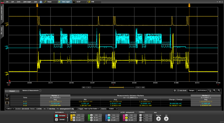
Power Profiler trace for the full boot sequence.
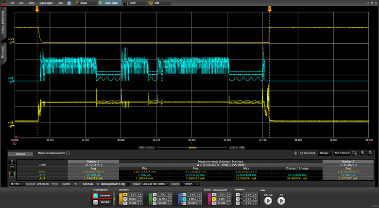
Power Profiler trace for one snapshot capture.
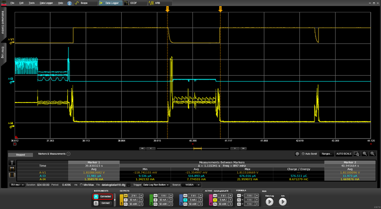
Power Profiler trace for one snapshot recovery.
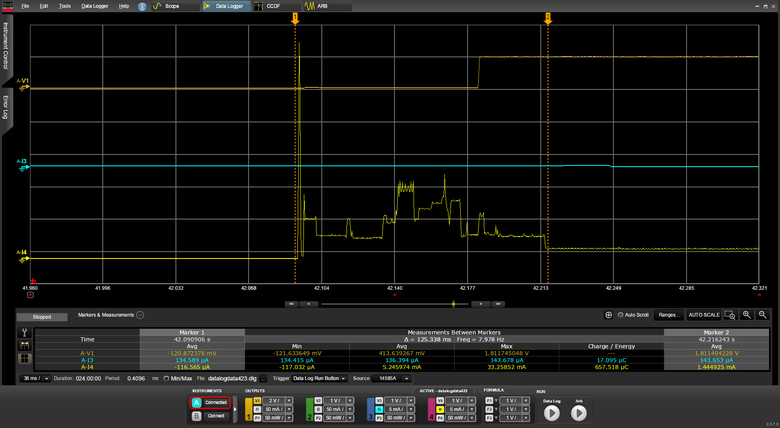
Power Profiler trace for boot without capture or recovery.
Dependencies
This sample uses the following nRF Connect SDK subsystems:
IronSide SE snapshot service - Captures and recovers configured MRAM and NVR regions
IronSide SE counter service - Tracks the boot cycle for the bounded capture/recovery flow
Sysbuild - Builds the application and UICR images together
UICR generation - Configures PROTECTEDMEM and snapshot regions in
sysbuild/uicr.conf
In addition, it uses the following Zephyr subsystems: