

Optimizing power consumption
The module manages its own power consumption. It continuously selects the most efficient internal configuration compatible with the current modem state, the configured power-saving parameters, and host interface activity.
Your host application does not select a sleep level, and the module does not expose one for configuration.
For current consumption figures, see the current consumption section of the nRF93M1 Datasheet.
System power modes
The module has three system-wide power modes.
Mode |
What is retained |
Entry |
Exit |
|---|---|---|---|
System ON |
Everything, including sockets, TLS and DTLS sessions, and network registration |
|
Automatic sleep and wake within the mode |
System OFF |
Network registration and configured wake sources. SRAM is not retained and ongoing tasks are terminated. |
|
Any configured wake source, or |
System Disabled |
Nothing. The module is deregistered from the network. |
Default after VDD is applied, |
|
Note
System OFF is opt-in.
The module does not enter it automatically as part of normal power saving.
Enable it with AT%SYSOFF=1, which requires UART1 at a fixed baud rate of 9600 or lower.
Automatic baud rate detection, or any higher rate, returns +CME ERROR: operation not allowed.
Read both the configured setting and the current state:
AT%SYSOFF?
%SYSOFF: 1,0
OK
The first value is the configured mode. The second value indicates whether the module has just woken from System OFF. Because the configuration survives a reset, a host can check the first value at startup to detect that a previous session left System OFF enabled.
Note
AT%POWD and AT%SYSOFF are not interchangeable.
AT%POWD enters System Disabled, which retains nothing, deregisters from the network, and can only be woken with POWERKEY followed by a full boot and attach.
AT%SYSOFF=1 enters System OFF, which retains network registration and has several wake sources.
Using AT%POWD where you intended System OFF produces a device that appears to have failed, because nothing except POWERKEY will bring it back.
Important
The System OFF configuration set by AT%SYSOFF=1 survives nRESET and a POWERKEY power cycle.
After a reset the module returns to System OFF rather than to normal operation.
Disable System OFF with AT%SYSOFF=0 before you change the UART configuration.
Configuring power saving
This section describes how to configure the power mode for power saving.
Enabling automatic power saving
Use the following AT command to enable automatic power saving on the device:
AT%MODULECFG="autoPowerSave",1
OK
There are following important constraints:
The setting can be changed only while the current sleep mode is System ON IDLE, so not while the module is already in power-saving sleep.
It takes effect when the radio is activated.
It is not retained across a reset, so your host must re-apply it after every restart.
Power saving is disabled at boot. Disabled is the correct configuration for RF testing, for provisioning, and for any period in which peripheral or general-purpose I/O functionality must stay available.
Note
Power saving does not engage before the modem attaches. During network search, registration, and attach retries the module draws its full System ON current. Budget for this if your device operates in marginal coverage, because repeated attach attempts can dominate the energy budget.
Tuning the wake window
AT%MODULECFG="slpWaitTime",<ms>
OK
This command sets how long the module stays awake after each wake-up. The default is 1000 ms. Reducing it lowers the average current on short duty cycles.
PSM
AT+CPSMS=1,,,"<T3412-ext>","<T3324>"
OK
The network sets the granted timer values and can reject PSM entirely. Operator-specific minimums apply. For example, some networks enforce a minimum T3412 of 190 minutes. Always read back the granted values instead of assuming your requested values were applied.
eDRX
AT+CEDRXS=2,4,"<eDRX value>"
OK
AT%PTWEDRXS=<paging time window settings>
OK
AT+CEDRXRDP
OK
%PTWEDRXS configures the Paging Time Window (PTW) together with the requested eDRX parameters.
You can request a PTW from 1.28 s to 20.48 s.
Operator minimums apply here as well.
For example, some networks enforce a minimum of 5.12 s.
AT+CEDRXRDP reads back the negotiated parameters.
eDRX and PSM are complementary and can be enabled together.
Connected DRX
AT%MODULECFG="pmuInCdrx",1
OK
1 allows deep sleep during connected DRX and is the default.
0 inhibits it.
Idle-mode DRX parameters are set by the network, and no host command changes them.
Designing the host wake path
UART1_DTR and UART1_RI let the host MCU and the module sleep and wake independently, with no data loss and without spending an extra GPIO.
- DTR is the host wake signal
Assert DTR to bring the module out of power-saving sleep before the host transmits.
- RI is the module’s data-ready signal
The module asserts RI when it has data for the host, and de-asserts it once it is ready to receive. RI can therefore serve as the host MCU’s own wake source, which lets the host sleep during idle periods.
The module buffers incoming network data while the host wakes, so nothing is lost even if the host is waking from a deep sleep state of its own.
With hardware flow control, the host watches its CTS pin, driven by the module’s UART1 RTS, to know when the module can accept data. A pull-up on the host CTS pin is required. Without hardware flow control, the host monitors RI, or waits at least the module wake latency between asserting DTR and its first transmit.
Important
DTR is the only host wake path that is independent of baud rate. Wake on incoming UART data requires UART1 at a fixed 9600 baud or lower before sleep is entered. A design that must keep UART1 at 115200 bps has to use DTR to wake the module.
Recommended configuration
The commands mentioned in the Configuring power saving section select the power mode.
The following settings reduce current further by disabling functions a deployed device does not need.
Apply them once during provisioning, and check that each returns OK before continuing.
AT+IPR=9600
OK
<change the host or terminal UART to 9600 bps>
AT%MODULECFG="ledMode",0
OK
AT%MODULECFG="logCtrl",0
OK
AT%MODULECFG="usbCtrl",2
OK
AT%MODULECFG="usbSlpMask",1
OK
AT%SIMCFG="SimPowerSave",1
OK
AT%SIMCFG="SimPresenceDetect",0
OK
Order matters for the first command.
AT+IPR=9600 takes effect immediately, so the host UART must change to 9600 bps before the remaining commands are sent.
The following settings remove wake sources:
SimPresenceDetect",0disables SIM hot-swap detection, so SIM presence transitions no longer wake the module.Leave presence detection enabled on designs with a user-accessible SIM slot that must react to a card being inserted or removed.
usbCtrl",2disables the USB device interface.Designs that rely on USB
VBUSdetect as a wake source, or that use USB for AT control, network data, or trace, should leave USB enabled and useusbSlpMaskalone to stop USB from holding the module awake.
Note
Disabling trace output with logCtrl",0 also disables the diagnostic stream Nordic technical support uses.
Re-enable it before capturing a trace for a support case.
Verifying behavior
A successful configuration command does not guarantee that the module sleeps.
To check the actual behavior, use the %SLEEPMODE URC, which the module emits on every sleep transition without requiring a subscription.
The URC reports the following modes:
|
Meaning |
|---|---|
0 |
Entering or returning to System ON Active |
2 |
Entering System ON Idle with power saving |
3 |
Entering System ON Idle with deep power saving |
4 |
Entering System OFF |
Mode 4 confirms that the module entered System OFF.
Repeated 0 transitions indicate that the host is waking the module more often than intended.
If the module does not appear to sleep, check the following in order:
autoPowerSaveis enabled and was reapplied after the last reset.The modem has attached to the network. Power saving does not engage before attach.
The network granted the PSM or eDRX parameters you requested.
USB is not holding the module awake. See
usbSlpMaskin Power consumption measurements.The host is not holding
UART1_DTRasserted.The host is not polling the module or enabling URCs that wake it. Polling on a timer raises the average current above the level the configured cycle would otherwise achieve.
The idle gaps are long enough for the module to enter a power-saving state. Very short gaps do not trigger a transition.
Power consumption measurements
The nRF93M1 achieves low power consumption through its System Disabled, System OFF, and System ON Idle operating states.
To measure each state in a simple, predictable, and repeatable way, the module provides two proprietary commands, %MODULECFG="autoPowerSave" and %SYSOFF, that place it in a known state on demand.
Do not use these commands in a final product, where power management is automated based on the host and LTE modem state.
The plots in the following sections were captured with the Power Profiler Kit II (PPK2). For details on connecting the PPK2 to the nRF93M1 DK, see section 4 in the nRF93M1 DK Hardware User Guide.
Note
Set UART1 to 9600 baud or lower with AT+IPR before the module enters System OFF.
At higher baud rates, UART data cannot wake the module and recovery requires POWERKEY or a power cycle.
Use DTR if the design must stay at 115200 bps.
Before you start any power measurements or use the power management commands, complete the following steps:
Set the module UART to 9600 bps, which enables the low-power UART mode that can wake the module from System OFF:
AT+IPR=9600
OK
Set your serial terminal software to 9600 bps.
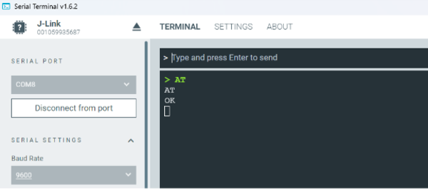
Serial Terminal with 9600 baud configurations
Configure the module for optimal power usage:
AT%MODULECFG="ledMode",0 // power off LED
OK
AT%MODULECFG="logCtrl",0 // disable log output
OK
AT%MODULECFG="usbCtrl",2 // disable USB
OK
AT%MODULECFG="usbSlpMask",1 // mask voting
OK
AT%SIMCFG="SimPowerSave",1 // enable SIM power save
OK
AT%SIMCFG="SimPresenceDetect",0 // disable SIM detection
OK
AT%MODULECFG="autoPowerSave",1  // Enable System ON Idle with power saving
OK
AT%MUCFG=1,4 // Enter System OFF mode
OK
Guidelines for exiting sleep
The AT+IPR command must set the UART to baud rate 9600 bps for the nRF93M1 to be able to wake-up from UART during deep sleep such as System OFF.
If the baud rate is set higher and the device enters deep sleep, the UART will not be able to wake up the module.
In such cases, you must use the POWERKEY pin or power cycle the device.
Before changing baud rate to values above 9600, make sure %SYSOFF is disabled or in System ON IDLE mode.
AT%SYSOFF?
%SYSOFF: 1,0
OK
AT%SYSOFF=0 // Disable System OFF mode
OK
AT+IPR=115200 // Baudrate now can be set to any value
OK
To reset the module completely, use AT%FACTORYRESET:
AT%FACTORYRESET
OK
A factory reset will also set the UART baud rate to the default value of 115200 bps.
Current measurements
To reproduce these results, set the UART to 9600 bps or lower, then enter System OFF as described in the Power consumption measurements section.
In the first measurement, the modem is set to minimal functionality:
AT+CFUN=0 // Modem set to minimal functionality
OK
The following plot is generated using the nRF Connect for Desktop Power Profiler app in source meter mode:
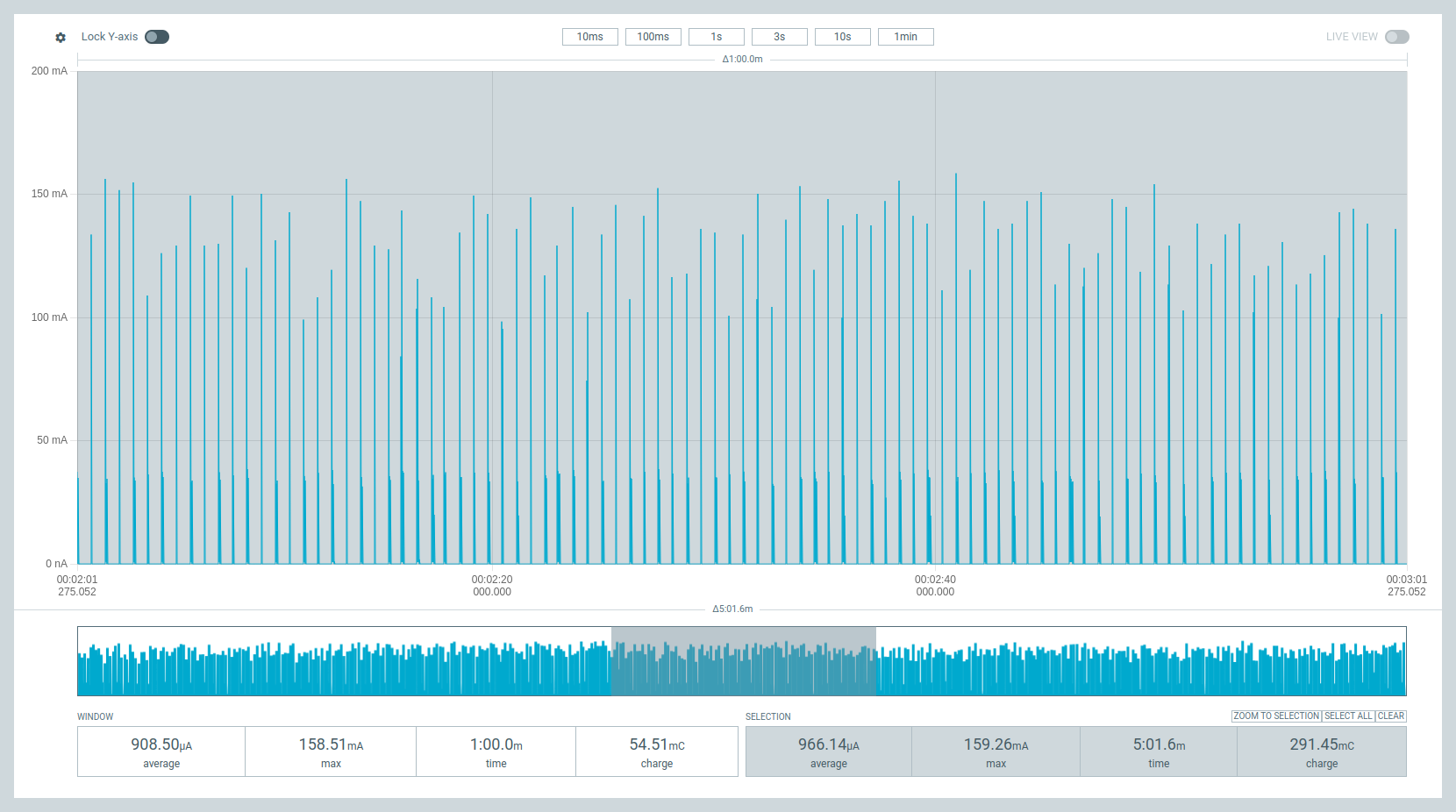
The average current in offline or flight mode is 2.03 µA.
The nRF93M1 is set in full functionality mode. During this measurement, the network configured the nRF93M1 to enter RCC Idle with a 640 ms DRX cycle.
AT+CFUN=1 // Modem set to full functionality
OK
The average current in RCC Idle with 640 ms DRX cycle is 345 µA.
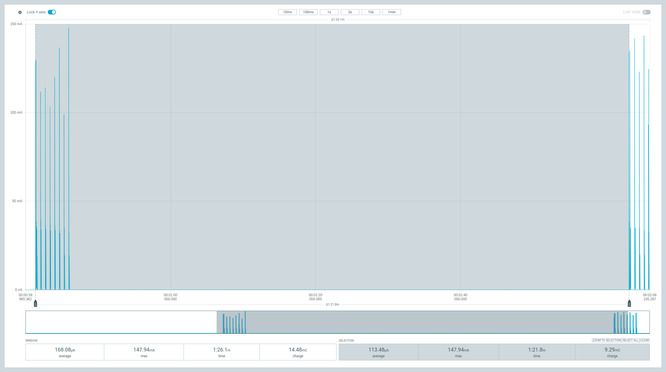
The nRF93M1 is configured to enter eDRX sleep mode and is granted 81.92 seconds eDRX intervals with 5.12 seconds Paging Time Window (PTW) and 640ms Paging Occasion.
Note
Most mobile networks have not yet rolled out eDRX support for LTE Cat 1 bis devices.
AT+CPSMS=0 // Disable PSM
OK
AT+CEDRXS=1,4,0101 // request eDRX interval of 81.92 seconds
OK
AT+CEDRXRDP // (optional) read eDRX dynamic parameters
+CEDRXRDP: 4,"0101","0101","0011"
OK
The average eDRX floor current is around 15.82 µA. The complete eDRX cycle average is 100 µA, including the 5.12 s PTW and 640 ms PO interval where the nRF93M1 will have 8 RX events with around 100 mA peak current.
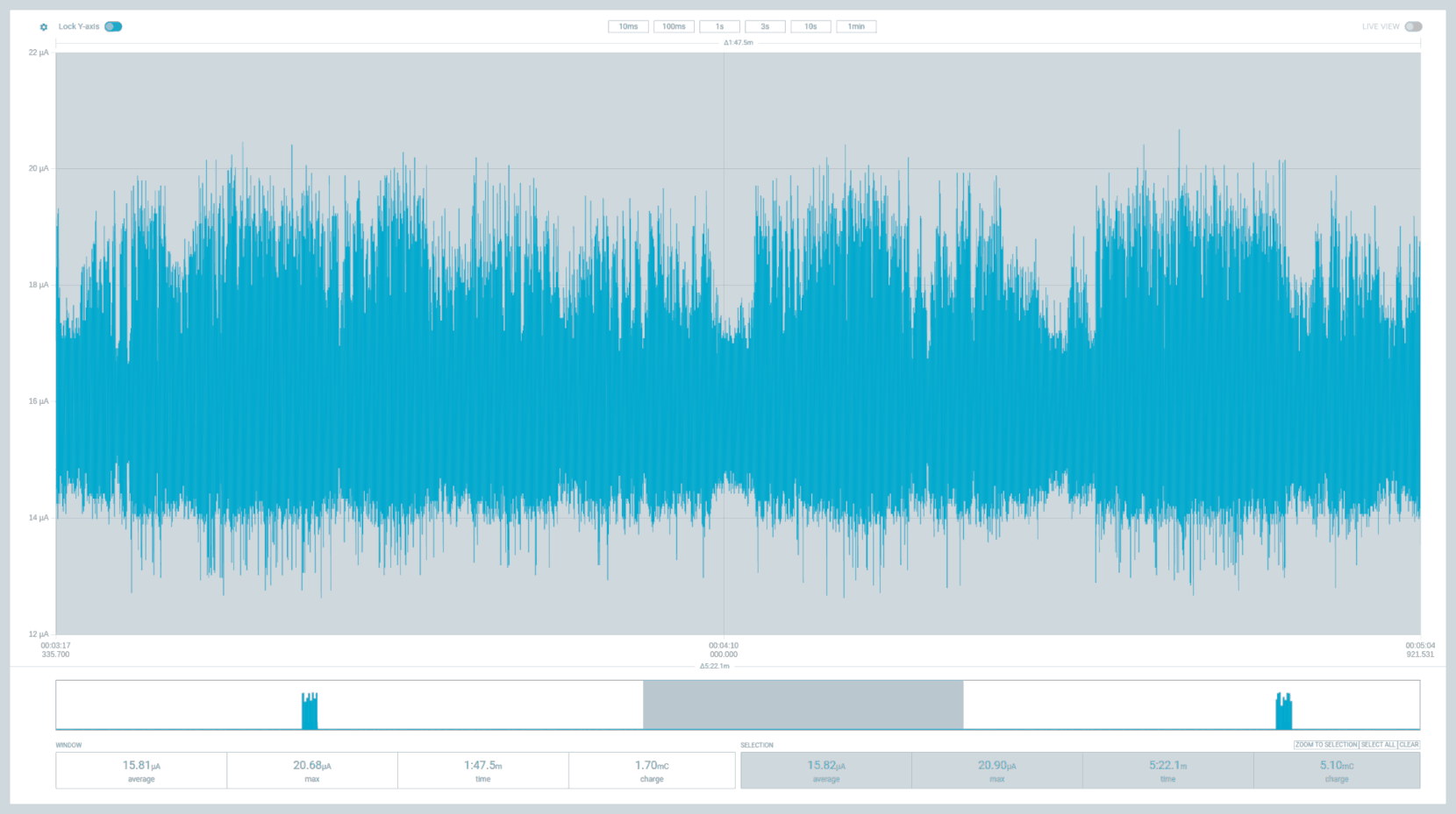
The nRF93M1 is now configured for PSM sleep, requesting a periodic update interval of 3600 seconds (1 hour) with an active time of 60 seconds.
AT+CEDRXS=0 // Disable eDRX
OK
AT+CPSMS=1,,,"00000110","00100001" // Request PSM 3600 seconds
OK
The average PSM floor current is around 2 µA.
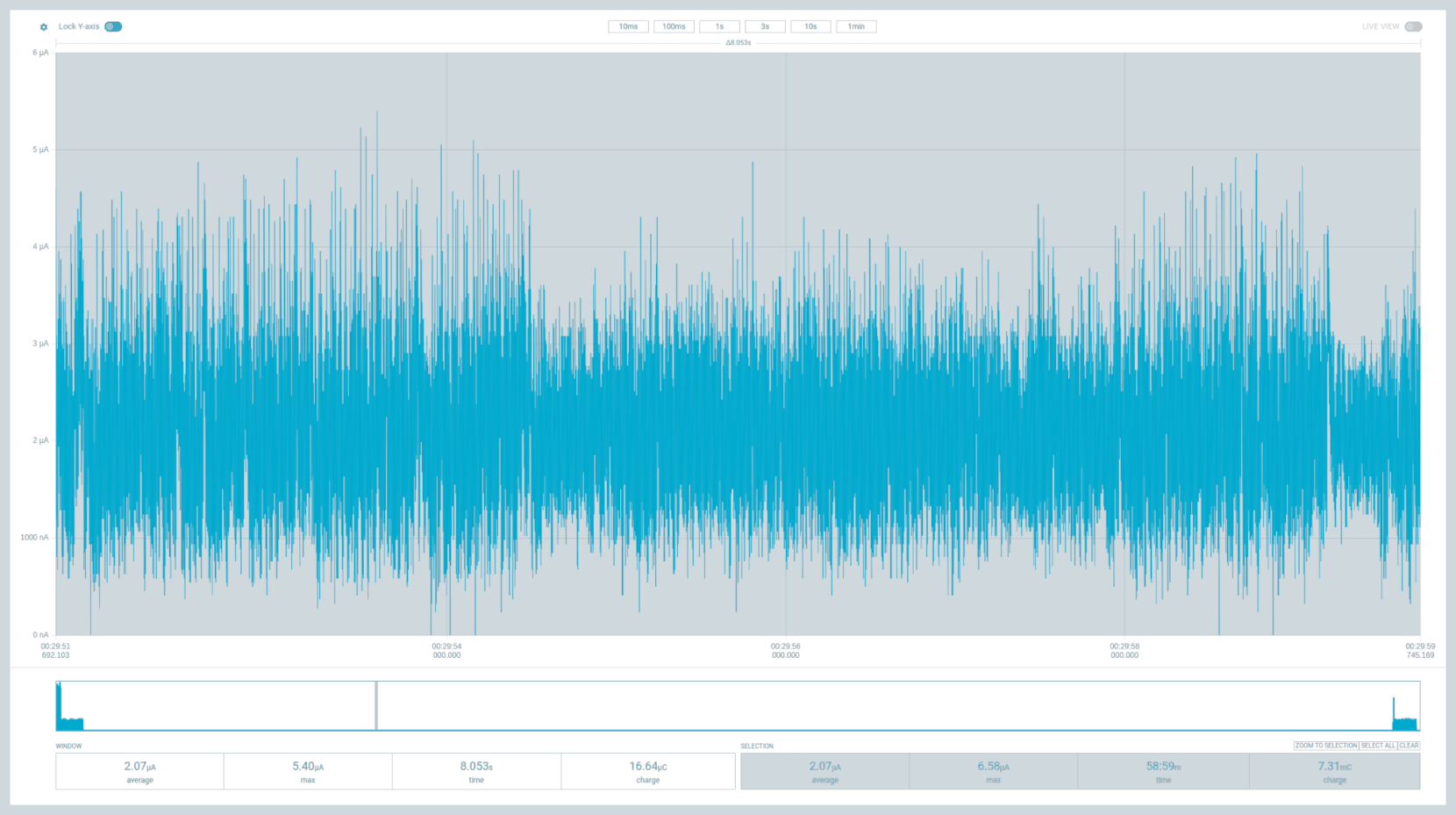
nRF93M1 PSM sleep current measurement
The following is the complete cycle that includes the Tracking Area Update (TAU) of 60 minutes and 60 seconds of active time, where the modem monitors for paging occasions (DRX) to receive any pending data for the network.
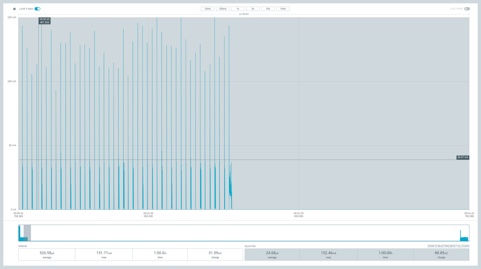
nRF93M1 PSM cycle with active time
The average current for the complete cycle is 24.68 µA.
Interpreting results
Differentiate the two numbers to avoid common confusion:
- Sleep current
The current drawn while the module is in a sleep state with nothing else happening. Useful for comparing states, but it does not predict battery life.
- Cycle average
The average current over a complete duty cycle, including wake, paging, transmit, and sleep. This is the number that determines battery life.
A sleep current figure quoted on its own overstates expected battery life, sometimes by an order of magnitude, because real duty cycles include periodic paging, transmission, and attach retries. Size batteries from a cycle average measured with your own traffic pattern, in coverage representative of your deployment.
Supply and temperature monitoring
The module exposes battery voltage and internal temperature:
AT%ADC="vbat"
AT%ADC="temp"
AT%ADC="all"
Threshold events arrive as %PALARM unsolicited result codes, covering a low-voltage alarm and a die-temperature alarm.
Important
%ADC and %PALARM monitoring work in System ON active operation only.
These domains are powered down during power-saving sleep.
Design guidance
Apply the following guidance when you design a battery-powered product around the nRF93M1.
- Choose the AT command model for battery designs
Running PPP on the host keeps the host IP stack alive and limits how deeply the host can sleep. See Host and modem architecture.
- Avoid USB as the data interface in battery designs
USB votes to keep the module awake. Use UART, and use
usbSlpMaskif USB must remain enabled.- Design wake around DTR, RI, USB
VBUS, or a 9600 baud UART General-purpose GPIO is not a wake path.
- Batch transmissions
Each wake and paging cycle costs energy. One larger message costs less than several small ones.
- Re-apply
autoPowerSaveafter every reset It is not retained. A device that silently stopped sleeping after a watchdog reset is a common field failure.