High-Performance Framework MSPI
Caution
The High-Performance Framework (HPF) support in the nRF Connect SDK is experimental and is limited to the nRF54L15, nRF54LM20A/B, nRF54LC10A, and nRF54LV10A devices.
This application demonstrates how to write a High-Performance Framework (HPF) application and communicate with it. The application implements a subset of the Zephyr MSPI API.
Application overview
The MSPI HPF application is structured into the following main components:
The HPF application - Operates on the FLPR core and facilitates data transmission between the application core and the connected MSPI device.
The Hard Real Time (HRT) module - Runs on the FLPR core and facilitates data transmission between the FLPR core and the connected MSPI device. The module emulates the MSPI hardware peripheral on the FLPR core, managing real-time data transmission and ensuring precise timing and synchronization of data transfer operations.
The MSPI Zephyr driver - Operates on the application core and uses the Zephyr’s scalable real-time operating system (RTOS) MSPI API for data and configuration transmission between the application and FLPR cores.
Scope
The application must meet the following key requirements:
Compatibility with the MSPI configuration including clock polarity, phase, and the number of data lines or transmission modes (single, quad).
Low latency and high throughput.
Requirements
The application supports the following development kits:
Hardware platforms |
PCA |
Board name |
|
|---|---|---|---|
nRF54LV10 DK |
PCA10188 |
|
|
PCA10184 |
|
||
nRF54LC10 DK |
PCA10226 |
nrf54lc10dk |
|
PCA10156 |
|
Configuration and data transfer management
Data transfer between the MSPI driver and the HPF application is done through the ICMsg.
Data can be configured to be passed either by copy or by reference.
By default, data is passed by reference.
To enable data passing by copy, you must disable the HPF_MSPI_IPC_NO_COPY and its MSPI driver-side equivalent MSPI_HPF_IPC_NO_COPY Kconfig options.
Initialization phase
The initialization of the MSPI HPF application is divided into two main phases: driver initialization and device initialization.
Driver initialization:
A user application calls the
mspi_config()function to initialize the MSPI driver.The MSPI driver passes the DTS pin configuration to the HPF application.
The HPF application calls the
config_pins()function to initialize GPIO settings based on the received configuration.All pins are assigned to specific VIO lines using a mapping array.
Device initialization
A user application calls the
mspi_dev_config()function to configure the MSPI device.The MSPI driver passes selected parts of the configuration to the HPF application.
The HPF application adds the device configuration to the device list.
Data transmission phase
The data transmission process is structured into two parts: preparation and the transfer.
Transfer preparation
A user application calls the
mspi_transceive()function to initiate a data transfer.The MSPI driver passes transfer parameters to HPF application (
hrt_xfer_t).The HPF application calls the
configure_clock()function to set the clock polarity and phase (SPI modes) based on thecpp_modeparameter. It ensures compatibility with modes 0 and 3.For each packet, MSPI driver passes packet data to HPF application, awaiting completion.
For each packet, HPF application calls the
xfer_execute()function to prepare the transfer and adjust the last word.
Note
Due to hardware constraints, the length of the last word cannot be
1. Theadjust_tail()function modifies the last two words to meet this requirement.Packet element transfer
Each packet transfer is initiated by the
hrt_write()orhrt_read()functions on the FLPR core. Additionally, each packet is divided into four elements:command,address,dummy_cycles, anddata.The
hrt_write()andhrt_read()functions prepare the hardware for data transmission by setting GPIO direction masks and determining active packet elements.The chip select (CS) is enabled before the transfer and disabled afterward unless
ce_holdis set totrue.Each TX packet element is processed using the
hrt_tx()function.hrt_read()function treats thedataelement as RX and passes all other elements to thehrt_write()function.For each packet element, the shift controller is configured for the appropriate number of data lines and word size.
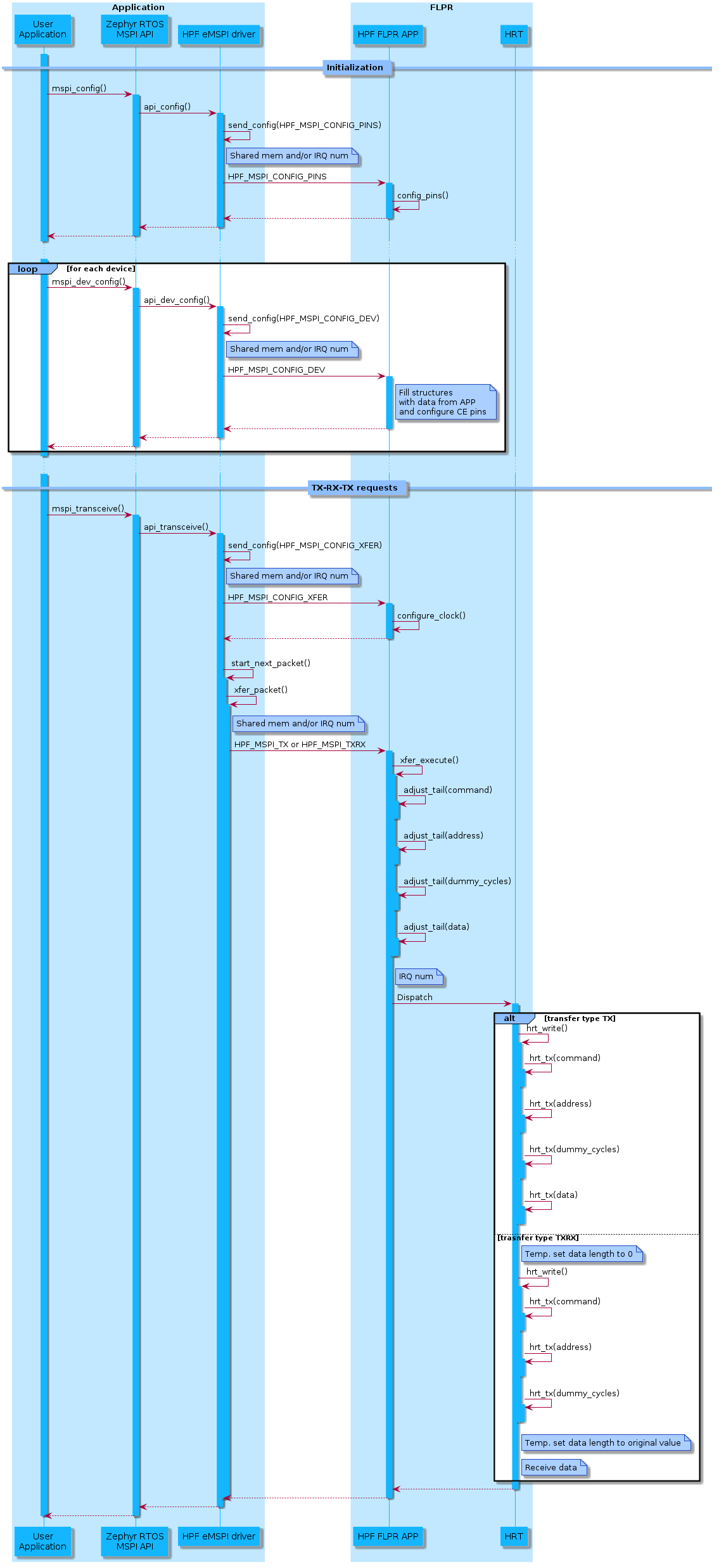
Sequence flow
The following diagram illustrates the interactions between the user application and the FLPR HRT, mapping out each step from initialization to data transfer:
Key functions
Key functions, such as hrt_write(), hrt_tx(), and hrt_read() are integral to managing the data transfer process, handling tasks from setting GPIO directions to executing low-level data transfers.
Function |
Purpose |
Key Steps |
|---|---|---|
The primary function for executing a TX transfer. It handles configuration, timing, and data transmission for all frame elements. |
|
|
|
Handles the low-level data transfer for a specific frame element (for example, |
|
The primary function for executing a RX transfer. It handles configuration, timing, and data transmission for all frame elements. |
|
|
|
Manages the formatting of the last and penultimate words in the transfer buffer to comply with hardware limitations. |
|
Key data structures
The following section provides an overview of the primary data structures used in managing MSPI transfers. These structures are crucial for configuring and executing data transfers efficiently.
Transfer elements
hrt_frame_element_t- Defines different frame elements (HRT_FE_COMMAND,HRT_FE_ADDRESS,HRT_FE_DUMMY_CYCLES,HRT_FE_DATA).
Transfer configuration
hrt_xfer_t- Encapsulates the core configuration for an MSPI transfer.xfer_data- An array of thehrt_xfer_data_tstructures for the frame elements (command,address,dummy_cycles,data).bus_widths- Defines the bit-width configuration for thecommand,address,dummy_cycles, anddatasections of the transfer.counter_value: Sets the clock divider to achieve frequency specified by a user.ce_vio- Index of the VIO pin used as CE.ce_hold- Whether CE remains asserted after the transfer.ce_polarity- Active polarity of the CE pin.tx_direction_maskandrx_direction_mask- Configure GPIO directions for data transmission.cpp_mode- SPI mode 0 or 3
Transfer data
hrt_xfer_data_t- Represents transfer-specific properties for each frame element.data- Points to the data being transmitted or received.word_count- Number of 32-bit words in the data buffer.last_word_clocks- Number of clock pulses for the final word.penultimate_word_clocks- Clock pulses for the second-to-last word.last_word- Holds the last word data (for transition or from reception).fun_out- Selects which function in TX to use to access buffered output register.
Building and running
This application can be found under applications/hpf/mspi in the nRF Connect SDK folder structure.
To build the application, follow the instructions in Building an application for your preferred building environment. See also Programming an application for programming steps and Testing and optimization for general information about testing and debugging in the nRF Connect SDK.
Note
When building repository applications in the SDK repositories, building with sysbuild is enabled by default.
If you work with out-of-tree freestanding applications, you need to manually pass the --sysbuild parameter to every build command or configure west to always use it.
To build and run the application, you must include code for both the application core and FLPR core. The process involves building a test or user application that is using MSPI driver with the appropriate sysbuild configuration.
You can use the tests listed in the Testing section. To build them, execute the following command in their respective directories:
west build -p -b <build_target>
Follow these steps to build with a user application:
Enable the following Kconfig options:
SB_CONFIG_HPF- Enables the High-Performance Framework (HPF).SB_CONFIG_HPF_MSPI- Integrates the HPF application image with the user application image.
Disable the following Kconfig options:
SB_CONFIG_VPR_LAUNCHER- Disables the default VPR launcher image for the application core.SB_CONFIG_PARTITION_MANAGER- Disables the Partition Manager.
Implement the business logic using the MSPI API with the HPF application.
Add device tree nodes that describe the chips connected via MSPI (hpf_mspi).
Compile your code.
Testing
The following tests utilize the MSPI driver along with this application:
nrf/tests/drivers/mspi/app_fault_timernrf/tests/drivers/mspi/error_casesnrf/tests/drivers/mspi/trap_handlernrf/tests/zephyr/drivers/mspi/apinrf/tests/zephyr/drivers/mspi/flashnrf/tests/zephyr/drivers/flash/common
These tests report results over the serial port, using the USB debug port on the nRF54L15, nRF54LM20, nrf54LC10 or nRF54LV10 DK.
Dependencies
zephyr/doc/services/ipc/ipc_service- Used for transferring data between application core and the FLPR core.nrf HAL - Enables access to the VPR CSR registers for direct hardware control.
Assembly management - Used to optimize performance-critical sections.
API documentation
Application uses the following API elements:
Zephyr driver
Header file:
include/drivers/mspi/hpf_mspi.hSource file:
drivers/mspi/mspi_hpf.c
FLPR application
Source file:
applications/hpf/mspi/src/main.c
FLPR application HRT
Header file:
applications/hpf/mspi/src/hrt/hrt.hSource file
applications/hpf/mspi/src/hrt/hrt.cAssembly:
applications/hpf/mspi/src/hrt/hrt-nrf54l15.sapplications/hpf/mspi/src/hrt/hrt-nrf54lm20a.sapplications/hpf/mspi/src/hrt/hrt-nrf54lm20b.sapplications/hpf/mspi/src/hrt/hrt-nrf54lc10a.sapplications/hpf/mspi/src/hrt/hrt-nrf54lv10a.s