Thread: CoAP Client
The Thread CoAP Client sample demonstrates controlling light resources of other nodes within an OpenThread network. To show this interaction, the sample requires a server sample that is compatible with the OpenThread network and has a light resource available. The recommended server sample referenced on this page is Thread: CoAP Server.
This sample supports optional Multiprotocol Bluetooth LE extension and Minimal Thread Device variant, which can be turned on or off. See Snippets for details.
Requirements
The sample supports the following development kits:
Hardware platforms |
PCA |
Board name |
|
|---|---|---|---|
PCA10184 |
|
||
nRF54LC10 DK |
PCA10226 |
nrf54lc10dk |
|
PCA10156 |
|
||
PCA10095 |
|
||
PCA10056 |
|
||
PCA10112 |
|
You can use one or more of the development kits listed above as the Thread CoAP Client. You also need one or more compatible development kits programmed with the Thread: CoAP Server sample.
Multiprotocol extension requirements
If you enable the Multiprotocol Bluetooth LE extension, make sure you have a phone with the nRF Toolbox application installed or an additional development kit programmed with Bluetooth: Central UART sample.
Note
The testing instructions refer to nRF Toolbox, but similar applications can be used as well, for example nRF Connect for Mobile.
Overview
This sample demonstrates how to access resources available on a Thread server node. After the Thread network is established, the client node can control the state of LEDs on server nodes. It can turn on the LED either on every server node in the network with a multicast message, or on a single specific server node that is paired with the client node.
The following CoAP resources are accessed on the server side:
/light- Used to control LEDs./provisioning- Used to perform provisioning.
This sample uses Zephyr CoAP API for communication, which is the preferred API to use for new CoAP applications. For example usage of the native Thread CoAP API, see the Thread: CoAP Server sample.
Multiprotocol Bluetooth LE extension
This optional extension demonstrates the OpenThread stack and SoftDevice Controller working concurrently. It uses the Nordic UART Service (NUS) library to control the LED states over Bluetooth® LE in a Thread network. For more information about the multiprotocol feature, see Multiprotocol support.
User interface
The following LED and buttons of the client development kit are used by this sample:
- LED 1:
On when the OpenThread connection is established.
- Button 1:
Send a unicast
LIGHT_TOGGLEmessage to the/lightresource on a paired device. If no device is paired with the specific client node, pressing the button has no effect.- Button 2:
Send a multicast
LIGHT_ONorLIGHT_OFFmessage (alternatively) to the/lightresource. Sending this multicast message instead ofLIGHT_TOGGLEallows to synchronize the state of the LEDs on several server nodes.- Button 4:
Send a multicast pairing request to the
/provisioningresource.
- LED 0:
On when the OpenThread connection is established.
- Button 0:
Send a unicast
LIGHT_TOGGLEmessage to the/lightresource on a paired device. If no device is paired with the specific client node, pressing the button has no effect.- Button 1:
Send a multicast
LIGHT_ONorLIGHT_OFFmessage (alternatively) to the/lightresource. Sending this multicast message instead ofLIGHT_TOGGLEallows to synchronize the state of the LEDs on several server nodes.- Button 3:
Send a multicast pairing request to the
/provisioningresource.
Minimal Thread Device assignments
When the device is working as Minimal Thread Device (MTD), the following LED and Button assignments are also available:
- Third LED:
The mode the device is working in:
On when in the Minimal End Device (MED) mode.
Off when in the Sleepy End Device (SED) mode.
- Third Button:
Toggle the power consumption between SED and MED.
For more information, see Device type options in the Thread user guide.
Multiprotocol Bluetooth LE extension assignments
- Second LED:
On when Bluetooth LE connection is established.
- UART command assignments:
The following command assignments are configured and used in nRF Toolbox when Testing multiprotocol Bluetooth LE extension:
u- Send a unicast CoAP message over Thread.m- Send a multicast CoAP message over Thread.p- Send a pairing request as CoAP message over Thread.
Configuration
See Configuring and building for information about how to permanently or temporarily change the configuration.
Multiprotocol
The multiprotocol feature enables the Thread CoAP Client sample to support both Thread and Bluetooth® LE functionality simultaneously. This allows the device to advertise and operate as a Bluetooth LE peripheral in addition to running a Thread network, enabling use cases such as Thread/Bluetooth firmware upgrades or Thread/Bluetooth device commissioning.
To enable the multiprotocol feature, run the following command with board_target replaced with the board target name:
west build -b board_target -p -- -DEXTRA_CONF_FILE=extra_conf/multiprotocol_ble.conf
Minimal Thread Device
The Minimal Thread Device feature enables the Thread CoAP Client sample to operate as a Minimal Thread Device (MTD). This allows the device to operate in low power mode when not actively participating in the Thread network. To enable the Minimal Thread Device feature, run the following command with board_target replaced with the board target name:
west build -b board_target -p -- -DEXTRA_CONF_FILE=extra_conf/mtd.conf
FEM support
You can add support for the nRF21540 front-end module to this sample by using one of the following options, depending on your hardware:
Build the sample for one board that contains the nRF21540 FEM, such as nRF21540 DK.
Manually create a devicetree overlay file that describes how the nRF21540 FEM is connected to the SoC. See Configuring devicetree for different ways of adding the overlay file.
Provide nRF21540 FEM capabilities by using a shield, for example the nRF21540 EK shield that is available in the nRF Connect SDK. In this case, build the project for a board connected to the shield you are using with an appropriate variable included in the build command, for example
-DSHIELD=nrf21540ek. This variable instructs the build system to append the appropriate devicetree overlay file.To build the sample in nRF Connect for VS Code for an nRF52840 DK with the nRF21540 EK attached, add the shield variable in the build configuration’s Extra CMake arguments and rebuild the build configuration. For example:
-DSHIELD=nrf21540ek.See How to work with build configurations in the nRF Connect for VS Code documentation for more information.
To build the sample from the command line for an nRF52840 DK with the nRF21540 EK attached, use the following command within the sample directory:
west build -b nrf52840dk/nrf52840 -- -DSHIELD=nrf21540ekSee Programming nRF21540 EK for information about how to program when you are using a board with a network core, for example the nRF5340 DK.
Each of these options adds the description of the nRF21540 FEM to the devicetree. See Developing with Front-End Modules for more information about FEM in the nRF Connect SDK.
To add support for other front-end modules, add the respective devicetree file entries to the board devicetree file or the devicetree overlay file.
Snippets
The sample supports Snippets for typical use cases, and to activate sample extensions.
You can find the OpenThread-related snippets in the snippets/openthread directory of the nRF Connect SDK main directory.
All snippets with the ot prefix are suitable for this sample.
Specify the corresponding snippet names in the coap_client_SNIPPET CMake option. For more information about using snippets, see Using Snippets in the Zephyr documentation.
To use the snippets, you need to add the sample name as a prefix before the SNIPPET CMake argument.
For example:
west build -b board_target -p -- -Dcli_SNIPPET="ot-logging;ot-usb"
The following snippets are available:
OpenThread snippet for CI purpose (ot-ci) - Disables boot banner and shel prompt.
OpenThread snippet for debugging purpose (ot-debug) - Enables logging using RTT and debugging the Thread sample by using
__ASSERT()statements globally. For additional options, refer to RTT logging.OpenThread snippet for diagnostic GPIO commands (ot-diag-gpio) - Configures DK’s Buttons and LEDs for diagnostic GPIO commands. For more information, see OpenThread Factory Diagnostics Module Reference.
OpenThread snippet for Zephyr L2 networking layer (ot-zephyr-l2) - Enables the Zephyr networking layer.
OpenThread snippet for USB transport (ot-usb) - Enables USB transport support.
Note
The OpenThread snippet for USB transport (ot-usb) does not support the
nrf54l15dk/nrf54l15/cpuappandnrf54l15dk/nrf54l10/cpuappboard targets because these platforms do not have USB peripheral.
Building and running
Make sure to enable the OpenThread stack before building and testing this sample. See Thread for more information.
This sample can be found under samples/openthread/coap_client in the nRF Connect SDK folder structure.
To build the sample, follow the instructions in Building an application for your preferred building environment. See also Programming an application for programming steps and Testing and optimization for general information about testing and debugging in the nRF Connect SDK.
Note
When building repository applications in the SDK repositories, building with sysbuild is enabled by default.
If you work with out-of-tree freestanding applications, you need to manually pass the --sysbuild parameter to every build command or configure west to always use it.
When building this sample with Sysbuild for an SoC that has a network core, the IPC radio firmware is automatically applied to the build.
The IPC radio is one of the companion components in the nRF Connect SDK and allows to use the radio peripheral from another core in a multicore device.
If needed, you can modify the IPC radio configuration in the prj.conf source file in the sample’s sysbuild/ipc_radio directory.
Testing
After building the sample and programming it to your development kit, test it by performing the following steps:
Program at least one development kit with Thread: CoAP Server and reset it.
Turn on the CoAP Client and at least one CoAP Server. They will create the Thread network.
Note
It may take up to 15 seconds for nodes to establish the network. When the sample application is ready, the LED 3 starts blinking.
Press Button 2 on a client node to control LED 4 on all server nodes.
Pair a client with a server by completing the following steps:
Press Button 4 on a server node to enable pairing.
Press Button 4 on a client node to pair it with the server node in the pairing mode.
Press Button 1 on the client node to control the LED 4 on the paired server node.
Program at least one development kit with Thread: CoAP Server and reset it.
Turn on the CoAP Client and at least one CoAP Server. They will create the Thread network.
Note
It may take up to 15 seconds for nodes to establish the network. When the sample application is ready, the LED 0 starts blinking.
Press Button 1 on a client node to control LED 3 on all server nodes.
Pair a client with a server by completing the following steps:
Press Button 3 on a server node to enable pairing.
Press Button 3 on a client node to pair it with the server node in the pairing mode.
Press Button 0 on the client node to control the LED 3 on the paired server node.
Testing Minimal Thread Device
After building the MTD variant of this sample and programming it, the device starts in the SED mode with LED 3 off. This means that the radio is disabled when idle and the serial console is not working to decrease the power consumption. You can switch to the MED mode at any moment during the standard testing procedure.
To toggle MED, press Button 3 on the client node. LED 3 turns on to indicate the switch to the MED mode. At this point, the radio is enabled when it is idle and the serial console is operating.
Pressing Button 3 again will switch the mode back to SED. Switching between SED and MED modes does not affect the standard testing procedure, but terminal logs are not available in the SED mode.
After building the MTD variant of this sample and programming it, the device starts in the SED mode with LED 2 off. This means that the radio is disabled when idle and the serial console is not working to decrease the power consumption. You can switch to the MED mode at any moment during the standard testing procedure.
To toggle MED, press Button 2 on the client node. LED 2 turns on to indicate the switch to the MED mode. At this point, the radio is enabled when it is idle and the serial console is operating.
Testing multiprotocol Bluetooth LE extension
To test the multiprotocol Bluetooth LE extension, you can use nRF Toolbox or the Bluetooth: Central UART sample. The steps below assume nRF Toolbox as the Bluetooth tester.
First, you need to set up nRF Toolbox as follows:
Tap UART to open the UART application in nRF Toolbox.
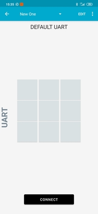
UART application in nRF Toolbox
Tap the EDIT button in the top right corner of the application to configure the UART commands. The button configuration window appears.
Create the active application buttons by completing the following steps:
Bind the top left button to the
ucommand, with EOL set to LF and an icon of your choice. For this testing procedure, the > icon is used.Bind the top middle button to the
mcommand, with EOL set to LF and an icon of your choice. For this testing procedure, the play button icon is used.Bind the top right button to the
pcommand, with EOL set to LF and an icon of your choice. For this testing procedure, the settings gear icon is used.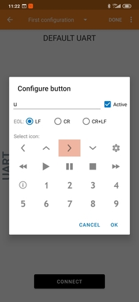
Configuring buttons in the UART application of nRF Toolbox
Tap the DONE button in the top right corner of the application.
Tap CONNECT and select the
NUS_CoAP_clientdevice from the list to connect to the device.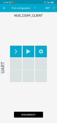
The UART application of nRF Toolbox after establishing the connection
Note
Observe that the second LED on your CoAP Multiprotocol Client node lights up, which indicates that the Bluetooth connection is established.
When you have set up nRF Toolbox, complete the following steps after the standard Testing procedure:
In nRF Toolbox, tap the middle button to control LED 4 on all CoAP server nodes.
To pair a client with a server, complete the following steps:
Press Button 4 on a server node to enable pairing.
In nRF Toolbox, tap the right button to pair the two nodes.
In nRF Toolbox, tap the left button to control LED 4 on the paired server node.
In nRF Toolbox, tap the middle button to control LED 3 on all CoAP server nodes.
To pair a client with a server, complete the following steps:
Press Button 3 on a server node to enable pairing.
In nRF Toolbox, tap the right button to pair the two nodes.
In nRF Toolbox, tap the left button to control LED 3 on the paired server node.
Sample output
You can observe the sample logging output with a terminal emulator that supports VT100/ANSI escape characters (for example, the Serial Terminal app). See Testing and optimization for the required settings and steps.
Dependencies
This sample uses the following nRF Connect SDK libraries:
In addition, it uses the following Zephyr libraries:
-
include/net/coap.h
-
include/logging/log.h
-
include/kernel.h
The following dependencies are added by the optional multiprotocol Bluetooth LE extension:
Zephyr’s API:
include/bluetooth/bluetooth.hinclude/bluetooth/gatt.hinclude/bluetooth/hci.hinclude/bluetooth/uuid.h