Trusted Firmware-M architecture
The following figure gives an overview of functionality and principles in Trusted Firmware-M (TF-M) and the entire firmware architecture in applications implementing TF-M in the nRF Connect SDK.
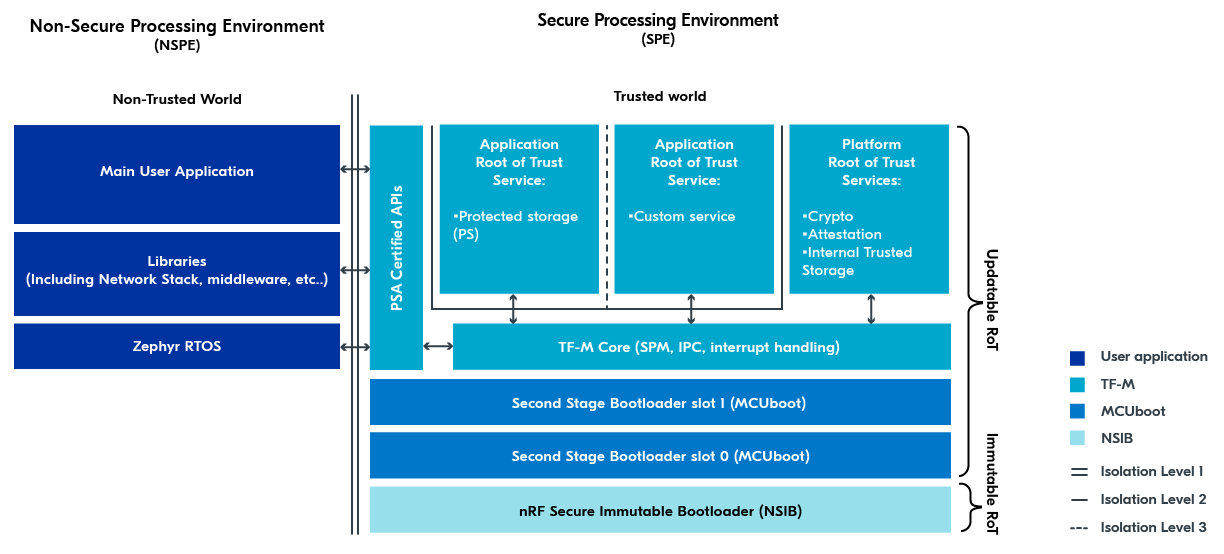
TF-M architecture overview
The sections that follow describe in brief different concepts mentioned on this figure, mostly related to the Secure Processing Environment (SPE).
For general information about this and other security architectures from Arm, see the Platform Security Architectures page.
Secure and Non-Secure Processing environments
The key TF-M concept is the security by separation into the Secure Processing Environment (SPE, Trusted world) and Non-Secure Processing Environments (NSPE, Non-Trusted world).
The Main User Application, Libraries (including the network stack and middleware), and the Zephyr RTOS seen under the Non-Secure Processing Environment (NSPE) represent the functional application firmware as it is normally known.
Trusted Firmware-M and bootloader components seen under the Secure Processing Environment (SPE) are isolated from the Non-Secure Processing Environment and implement security-critical functionality.
Multiple levels of isolation can be achieved between the environments through a combination of ARM TrustZone and other hardware memory protection features.
See Security by separation and processing environments for more information.
Immutable RoT and Updatable RoT
TF-M implements two types of Root of Trust (RoT) in the Chain of Trust:
Immutable Root of Trust (Immutable RoT) - “The combination of hardware and non-modifiable firmware and data installed during manufacturing” (as per Trusted Base System Architecture for M (TBSA-M) Specification). For the nRF5340 and nRF9160 devices, the Immutable RoT consists of an Immutable bootloader, plus certain hardware peripherals such as the Key Management Unit (KMU) and One-Time Programmable (OTP) memory.
Updatable Root of Trust (Updatable RoT) - The remainder of the components in the SPE. This includes amongst other the second stage bootloader, TF-M’s Secure Partition Manager (SPM), and the Root of Trust services.
You can read more about RoT and Chain of Trust in the nRF Connect SDK in the bootloader documentation. Additional information is also available in the What is a Root of Trust? blog post on the PSA Certified website.
Immutable Bootloader and Second Stage Bootloader
Bootloaders ensure that all software being executed has been authorized and that your application is protected against running altered code. In addition, a bootloader is required to perform security updates that fix eventual vulnerabilities or adds new security features.
For information about bootloader concepts and bootloaders available in the nRF Connect SDK, see the Bootloaders and DFU section, in particular the MCUboot and NSIB.
Application and Platform Root of Trust Services
The SPE has a set of services available for use. These are known as Root of Trust Services (RoT Services).
All RoT Services are available inside the Secure image. RoT Services can be made available to the Non-Secure image through the PSA Certified API’s Non-Secure Callable Interface, a security mechanism that enables controlled communication between NSPE and SPE.
Platform RoT Services
Defined by the section 7 in the ARM Platform Security Model 1.1, the Platform RoT Services are a set of mandatory RoT Services:
Crypto: An RoT Service that provides an API to cryptographic operations, such as securely generating, storing, or accessing keys. For more information, see TF-M Crypto Service implementation, PSA Crypto API, the PSA Certified Crypto API and the Cryptographic samples.
Attestation: “The Initial Attestation Service (IAS) provides a signed Initial Attestation Token (IAT). The IAT includes the state of the Platform Root-of-Trust, including whether a debug state has been entered, and any claims made by AEP.” For a detailed explanation of attestation, see Device Attestation and Entity Attestation Tokens Explained blog post on the PSA Certified website.
Internal Trusted Storage (ITS): A RoT Service that provides trusted storage of key material in internal flash.
Note
The PSA Crypto APIs provide functionality to manage keys stored in the PSA ITS. Therefore, there is no need to expose PSA ITS as a secure service to the Non-Secure image.
Application RoT Services
The Application RoT Services are application-specific services, meaning that they can be included if needed by the application.
Some Application RoT Services are pre-defined, but you can add custom Application RoT Services. For example:
Protected Storage - A RoT Service that provides secure storage capabilities for non-volatile data present in the NSPE. For more information about this service, see PSA Secure Storage API, PSA Certified Secure Storage API 1.0 and Zephyr’s TF-M PSA Protected Storage. For information about how to enable it, see Protected Storage service.
Other custom Application RoT Services - See the TF-M secure peripheral partition sample that demonstrates how to create a custom Application RoT Service.
The main difference between this Protected Storage API and the ITS API is that ITS is only used from the SPE, while Protected Storage is exposed to the NSPE through the IPC. See PSA Certified Secure Storage API 1.0 for more information on the difference between them (especially section 1.1, Use Cases and Rationale).
Note
In the TF-M architecture overview figure, a line separates Application RoT Services from the rest of the SPE. This separation is described in the Isolation Levels section.
PSA Certified API
The Non-Secure image cannot access the Secure image directly. Instead, the Non-Secure image can call on the PSA Certified APIs using the TF-M Crypto Service implementation to get access to the Application RoT Services as well as a subset of the Platform RoT Services.

TF-M Crypto Service implementation in the NSPE and SPE
The PSA Certified APIs are exposed to the Non-Secure side using the Non-Secure Callable Interface, a security mechanism that enables controlled communication between NSPE and SPE. Using this mechanism, the application running in the NSPE can securely communicate with RoT Services in the SPE. For example, the Non-Secure application can call the psa_generate_random() function to get a secure random number generated from the Secure image.
For details on the hardware implementation of Non-Secure Callable Interface, see the System Protection Unit (SPU) documentation in the respective datasheet. For example, in the nRF9160 Product Specification, the nRF9161 Product Specification, or the nRF54L15 Datasheet, to name a few.
Note
The representation of the NSPE in the TF-M architecture figure at the top of this page serves only to visualize that there are multiple modules inside the Non-Secure image that makes use of PSA Certified APIs. TF-M provides only a single entry-point for reaching the Non-Secure Callable interface.
TF-M Core
TF-M Core is the internal TF-M functionality responsible for isolation, communication and execution within SPE and with NSPE. The user application does not need to directly interface with TF-M Core, because it automatically operates in the background of the TF-M implementation. For completeness sake, TF-M Core has the following functionalities:
Uses TF-M’s Secure Partition Manager (SPM) to configure Secure/Non-Secure flash and memory.
Uses TF-M’s Secure Partition Manager (SPM) to initialize Secure/Non-Secure hardware peripherals
Uses TF-M’s Inter-Process Communication (IPC) to allow communication between the Secure and Non-Secure images.
Uses TF-M’s Inter-Process Communication (IPC) to allow communication between services inside the Secure images.
Handles interrupts in a secure way. See TF-M’s Secure Interrupt Integration for more information.
More documentation on TF-M’s Inter-Process Communication (IPC) can also be found in the Trusted Base System Architecture for M (TBSA-M) Specification.
Note
The nRF Connect SDK v2.1.0 and earlier provided a module called Secure Partition Manager (SPM) to handle the Secure/Non-Secure separation. This has the same name as TF-M’s Secure Partition Manager (SPM). These two modules are not the same.
The TF-M architecture figure at the top of this page visualizes the communication flow with PSA Certified API using the arrows to and from TF-M Core.
Isolation Levels
The TF-M architecture figure at the top of this page uses several lines as connectors and separators. These lines represent the isolation levels between different parts of the SPE and between the SPE and the NSPE.
The following table describes the isolation levels in the TF-M architecture, based on the Trusted Base System Architecture for M (TBSA-M) Specification (section 4.3) and the FF-M Isolation Rules.
Isolation Level |
Description |
|---|---|
Level 1 |
Two security domains
SPE isolation
SPE is protected from access by Non-Secure application firmware and hardware.
|
Level 2 |
Platform RoT isolation
Three security domains
In addition to Level 1, the Platform RoT is also protected from access by the Application RoT.
|
Level 3 |
Three or more security domains
Maximum firmware isolation
In addition to Level 2, each Secure Partition is sandboxed and only permitted to access its own resources.
This protects each Secure Partition from access by other Secure Partitions and protects the SPM from access by any Secure Partition.
|
In other words:
Level 1 Isolation is the Secure/Non-Secure separation described in the Secure and Non-Secure Processing environments section.
Level 2 Isolation means that the Application RoT Services are unable to access other parts of the SPE.
Level 3 Isolation means that the Application RoT Services are unable to access other parts of the SPE and other Application RoT Services. Level 3 Isolation is not supported in the nRF Connect SDK.