SAM R34 Xplained Pro Evaluation Kit
Overview
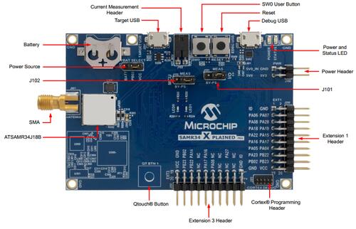
The SAM R34 Xplained Pro evaluation kit is ideal for evaluation and prototyping with the SAM R34 Cortex®-M0+ processor-based microcontrollers. The kit includes Atmel’s Embedded Debugger (EDBG), which provides a full debug interface without the need for additional hardware.
The SAMR34 and SAMR35 parts are produced as a System-in-Package (SiP), including both a SAML21 die, and a Semtech SX1276 LoRa radio die.
This board is also referred to as DM320111.
Hardware
SAMR34J18 ARM Cortex-M0+ processor at 48 MHz
32.768 kHz crystal oscillator
256 KiB flash memory, 32 KiB of SRAM, 8KB Low Power SRAM
One yellow user LED
One mechanical user push button
One reset button
On-board USB based EDBG unit with serial console
Supported Features
The samr34_xpro board supports the hardware features listed below.
- on-chip / on-board
- Feature integrated in the SoC / present on the board.
- 2 / 2
-
Number of instances that are enabled / disabled.
Click on the label to see the first instance of this feature in the board/SoC DTS files. -
vnd,foo -
Compatible string for the Devicetree binding matching the feature.
Click on the link to view the binding documentation.
Pin Mapping
The SAM R34 Xplained Pro evaluation kit has 3 GPIO controllers. These controllers are responsible for pin muxing, input/output, pull-up, etc.
For more details please refer to SAM R34 Family Datasheet [1] and the SAM R34 Xplained Pro Schematic [2].
Default Zephyr Peripheral Mapping:
SERCOM0 UART TX : PA04
SERCOM0 UART RX : PA05
SERCOM1 I2C SDA : PA16
SERCOM1 I2C SCL : PA17
SERCOM4 SPI MISO : PC19
SERCOM4 SPI MOSI : PB30
SERCOM4 SPI SCK : PC18
SERCOM4 GPIO CS : PB31
SERCOM5 SPI MISO : PB02
SERCOM5 SPI MOSI : PB22
SERCOM5 SPI SCK : PB23
SERCOM5 GPIO CS0 : PA23
SERCOM5 GPIO CS1 : PA14
USB DP : PA25
USB DM : PA24
GPIO/PWM LED0 : PA19
System Clock
The SAMR34 MCU is configured to use the 32.768 kHz external oscillator with the on-chip PLL generating the 48 MHz system clock.
Serial Port
The SAMR34 MCU has six SERCOM based USARTs with one configured as USART in this BSP. SERCOM0 is the default Zephyr console.
SERCOM0 115200 8n1 - connected to the onboard Atmel Embedded Debugger (EDBG)
PWM
The SAMR34 MCU has 3 TCC based PWM units with up to 4 outputs each and a period
of 24 bits or 16 bits. If CONFIG_PWM_SAM0_TCC is enabled then LED0 is
driven by TCC0 instead of by GPIO.
SPI Port
The SAMR34 MCU has 6 SERCOM based SPIs, with two configured as SPI in this BSP.
SERCOM4 - connected to the internal LoRa radio
SERCOM5 - connected to EXT1 and EXT3
Programming and Debugging
The samr34_xpro board supports the runners and associated west commands listed below.
| flash | debug |
|---|
The SAM R34 Xplained Pro comes with a Atmel Embedded Debugger (EDBG). This provides a debug interface to the SAMR34 chip and is supported by OpenOCD.
Flashing
Build the Zephyr kernel and the
hello_worldsample application:west build -b samr34_xpro samples/hello_world
Connect the SAM R34 Xplained Pro to your host computer using the USB debug port.
Run your favorite terminal program to listen for output. Under Linux the terminal should be
/dev/ttyACM0. For example:$ picocom -b 115200 /dev/ttyACM0
Speed: 115200
Data: 8 bits
Parity: None
Stop bits: 1
To flash an image:
west build -b samr34_xpro samples/hello_world
west flash
You should see “Hello World! samr34_xpro” in your terminal.