RP2040-Plus
Overview
RP2040-Plus, a low-cost, high-performance Pico-like MCU board based on Raspberry Pi microcontroller RP2040 including a battery charger.
Hardware
Dual core Arm Cortex-M0+ processor running up to 133MHz
264KB on-chip SRAM
4MB/16MB on-board QSPI flash with XIP capabilities
26 GPIO pins
3 Analog inputs
2 UART peripherals
2 SPI controllers
2 I2C controllers
16 PWM channels
USB 1.1 controller (host/device)
8 Programmable I/O (PIO) for custom peripherals
On-board LED
1 Watchdog timer peripheral
on-board battery charger
Supported Features
The rp2040_plus board supports the hardware features listed below.
- on-chip / on-board
- Feature integrated in the SoC / present on the board.
- 2 / 2
-
Number of instances that are enabled / disabled.
Click on the label to see the first instance of this feature in the board/SoC DTS files. -
vnd,foo -
Compatible string for the Devicetree binding matching the feature.
Click on the link to view the binding documentation.
Pin Mapping
The peripherals of the RP2040 SoC can be routed to various pins on the board. The configuration of these routes can be modified through DTS. Please refer to the datasheet to see the possible routings for each peripheral.
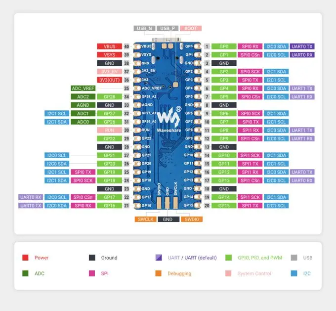
Default Zephyr Peripheral Mapping:
UART0_TX : P0
UART0_RX : P1
I2C0_SDA : P4
I2C0_SCL : P5
I2C1_SDA : P6
I2C1_SCL : P7
SPI0_RX : P16
SPI0_CSN : P17
SPI0_SCK : P18
SPI0_TX : P19
ADC_CH0 : P26
ADC_CH1 : P27
ADC_CH2 : P28
Programming and Debugging
The rp2040_plus board supports the runners and associated west commands listed below.
| flash | debug |
|---|
Flashing
Using UF2
Here is an example of building the sample for driving the built-in led.
west build -b rp2040_plus samples/basic/blinky
You must flash the RP2040-Plus with an UF2 file. One option is to use West (Zephyr’s meta-tool). To enter the UF2 flashing mode just keep the BOOT button pressed while you connect the USB port, it will appear on the host as a mass storage device. In alternative with the board already connected via USB you can keep the RESET button pressed, press and release BOOT, release RESET. At this point you can flash the image file by running:
west flash
Alternatively, you can locate the generated build/zephyr/zephyr.uf2 file and simply drag-and-drop to the device after entering the UF2 flashing mode.