IT51XXX series
Overview
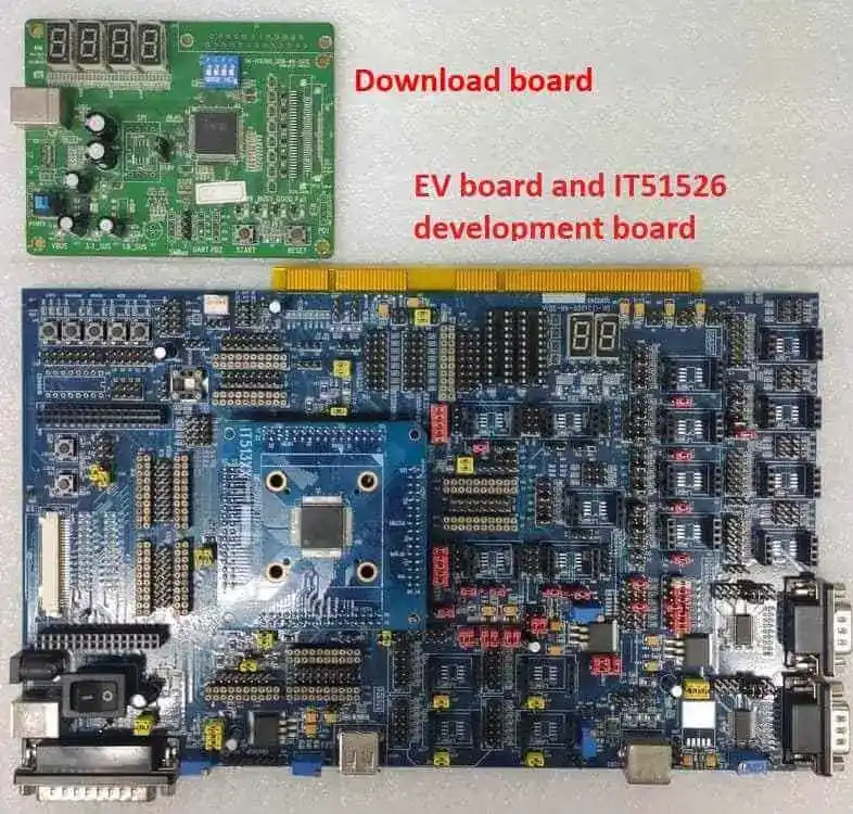
The IT51XXX is a 32-bit RISC-V microcontroller. And a highly integrated embedded controller with system functions. It is suitable for mobile system applications. The picture below is the IT51526 development board (also known as it51xxx_evb/it51526aw) and its debug card.
To find out more about ITE, visit our World Wide Web at:ITE’s website [1]
Hardware
The IT51XXX series contains different chip types(ex, it51526, it51527), and they support different hardware features. Listing the IT51526 hardware features as following:
RISC-V RV32IMC instruction set
4KB instruction cache size
128KB SRAM in total
Built-in 32.768 kHz clock generator
Embedded Flash, 512K/1024K-byte e-flash
eSPI, SPI, BRAM, KBC, PECI, UART
GPIO, PWM, ADC, INTC, WUC, Timer, Watchdog, KB scan, JTAG
Support 3 Voltage Comparator
Support Cryptographic Engine
9 SMBus hosts, 3 targets, with 12 SMBus channels, compatible with I2C
I3C host: Support two I3C controllers, compliant with the MIPI I3C v1.0 SEPC.
Two-wire serial interface up to 12.5MHz using Push-Pull.
Support SDR, IBI, Hot-Join.
I3C target: Support SDR, FIFO co-use DLM. Support Push-Pull output.
Supported Features
The it51xxx_evb board supports the hardware features listed below.
- on-chip / on-board
- Feature integrated in the SoC / present on the board.
- 2 / 2
-
Number of instances that are enabled / disabled.
Click on the label to see the first instance of this feature in the board/SoC DTS files. -
vnd,foo -
Compatible string for the Devicetree binding matching the feature.
Click on the link to view the binding documentation.
Programming and debugging on it51526
In order to upload the application to the device, you’ll need our flash tool and Download board. You can get them at: ITE’s website [1].
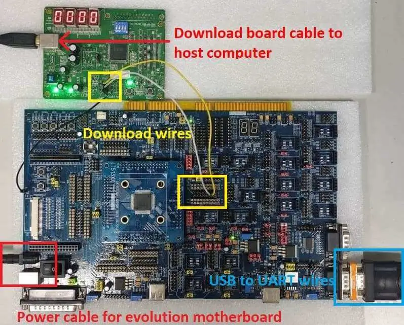
Wiring
Connect the Download Board to your host computer using the USB cable.
Connect the it51xxx_evb to the evolution motherboard.
Connect the Download Board J5 to J38(GPC1 & GPC2) on the evolution motherboard.
Connect the USB to UART wire to UART0 connector on the evolution motherboard.
Note
Be careful during connection! Use separate wires to connect I2C pins with pins on the it51xxx_evb board. Wiring connection is described in the table below.
J5 Connector
it51xxx_evb J38 Connector
2
C1
3
C2
4
GND
For USB to UART cable, connect the evolution motherboard as below:
USB to UART cable
Evolution motherboard UART0 Connector
USB
UART0
Building
Build Hello World application as you would normally do (see :Zephyr Getting Started Guide [2]):.
# From the root of the zephyr repository
west build -b it51xxx_evb/it51526aw samples/hello_world
The file
zephyr.binwill be created by west.
Flashing
Windows
Use the winflash tool to program a zephyr application to the it51xxx/it51526aw board flash.
Flashing steps as described in the link: Flashing steps [3].
Turn on the it51xxx_evb/it51526aw board switch, you should see
"Hello World! it51xxx_evb/it51526aw"sent by the board. If you don’t see this message, press the Reset button and the message should appear.
Ubuntu
Run your favorite terminal program to listen for output. Under Linux the terminal should be
/dev/ttyUSB0. Do not close it.For example:
$ minicom -D /dev/ttyUSB0 -b 115200
Open a second terminal window and use the Linux flash tool to flash your board.
$ sudo ~/itetool/ite -f build/zephyr/zephyr.bin
Note
The source code of ITE tool can be downloaded here: https://www.ite.com.tw/upload/2024_01_23/6_20240123162336wu55j1Rjm4.bz2
Split first and second terminal windows to view both of them. You should see
"Hello World! it51xxx_evb/it51526aw"in the first terminal window. If you don’t see this message, press the Reset button and the message should appear.
Debugging
it51xxx_evb board can be debugged by connecting USB to UART. We can write commands and read messages through minicom in the Ubuntu terminal.
Troubleshooting
If the flash tool reports a failure, re-plug the 8390 Download board or power cycle the it51xxx_evb board and try again.