BL654 USB (451-00004)
Overview
The BL654 USB adapter hardware (Ezurio part 451-00004) provides support for the Ezurio BL654 module powered by a Nordic Semiconductor nRF52840 ARM Cortex-M4F CPU.
The BL654 USB adapter has the following features:
CLOCK
FLASH
GPIO
MPU
NVIC
PWM
RADIO (Bluetooth Low Energy and 802.15.4)
RTC
USB
WDT
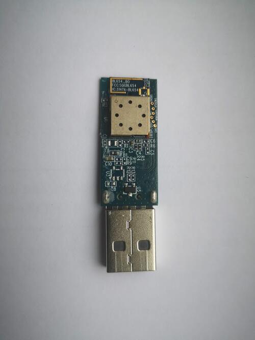
BL654 USB Adapter PCB
More information about the BL654 USB adapter can be found in the BL654 USB Dongle Quick Start Guide [1]. There is more information on the BL654 range on the BL654 website [2].
Hardware
The bl654_usb has two external oscillators. The frequency of
the slow clock is 32.768 kHz. The frequency of the main clock
is 32 MHz.
Supported Features
The bl654_usb board supports the hardware features listed below.
- on-chip / on-board
- Feature integrated in the SoC / present on the board.
- 2 / 2
-
Number of instances that are enabled / disabled.
Click on the label to see the first instance of this feature in the board/SoC DTS files. -
vnd,foo -
Compatible string for the Devicetree binding matching the feature.
Click on the link to view the binding documentation.
See the BL654 website [2] for a complete list of BL654 USB adapter hardware features.
Connections and IOs
LED
LED1 (blue) = P0.13
Serial Port
Zephyr console output is available as follows:
using the USB connector, which may be used to make the console available on PC as USB CDC class.
Programming and Debugging
The bl654_usb board supports the runners and associated west commands listed below.
| flash | debug |
|---|
Applications for the bl654_usb board configuration can be
built in the usual way (see Building an Application for more details). The
bl654_usb board can be used for debugging, but the compatible BL654 DVK
board may be preferable for convenience. Documentation can be found at the BL654 DVK
site and boards/ezurio/bl654_dvk/doc/bl654_dvk.rst
Flashing
The board supports the following programming options:
Using the built-in bootloader only
Using an external debug probe
These instructions use the west tool and assume you are in the root directory of your west installation.
Option 1: Using the Built-In Bootloader Only
The board is factory-programmed with Nordic’s bootloader from Nordic’s nRF5 SDK. With this option, you’ll use Nordic’s nrfutil [4] program to create firmware packages supported by this bootloader and flash them to the device. Before proceeding make sure:
nrfutilis installed.The
nrf5sdk-toolscommand is installed withinnrfutil.
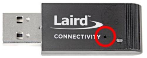
With the adapter plugged in, reset the board into the bootloader by pressing the RESET button.
The push button is in a pin-hole on the logo side of the USB adapter.
The blue LED should start a fade pattern, signalling the bootloader is running.
Compile a Zephyr application; we’ll use Blinky.
west build -b bl654_usb zephyr/samples/basic/blinky
Package the application for the bootloader using
nrfutil:nrfutil nrf5sdk-tools pkg generate \ --hw-version 52 \ --sd-req=0x00 \ --application build/zephyr/zephyr.hex \ --application-version 1 \ blinky.zip
Flash it onto the board. Note
/dev/ttyACM0is for Linux; it will be something likeCOMxon Windows, and something else on macOS.nrfutil nrf5sdk-tools dfu usb-serial -pkg blinky.zip -p /dev/ttyACM0When this command exits, observe the blue LED on the board blinking, instead of the fade pattern used by the bootloader.
For more information, see Nordic Semiconductor USB DFU [3].
Option 2: Using an External Debug Probe
If you have one, you can also use an external debug probe to flash and debug Zephyr applications, but you need to solder an SWD header to the board. Connection points can be found in the board schematics [5].
For Segger J-Link debug probes, follow the instructions in the Nordic nRF5x Segger J-Link page to install and configure all the necessary software. Further information can be found in Flashing.
Use the bl654_usb/bare board variant to build your application.
This variant uses a modified partition table, which does not reserve space for
the onboard USB bootloader.
Then build and flash applications as usual (see Building an Application and Run an Application for more details).
Here is an example for the Blinky application.
# From the root of the zephyr repository
west build -b bl654_usb/nrf52840/bare samples/basic/blinky
west flash
Observe the LED on the board blinking.
Debugging
The bl654_usb board does not have an on-board J-Link debug IC
as some Ezurio development boards, however, instructions from the
Nordic nRF5x Segger J-Link page also apply to this board, with the additional step
of connecting an external debugger.
Testing the LED on the BL654 USB
There is a sample that allows you to test that the LED on the board is working properly with Zephyr:
You can build and flash the example to make sure Zephyr is running correctly on your board. The LED definitions can be found in boards/ezurio/bl654_usb/bl654_usb.dts.
Testing Bluetooth on the BL654 USB
Many of the Bluetooth examples will work on the BL654 USB. Try them out: