OLIMEX-STM32-H407
Overview
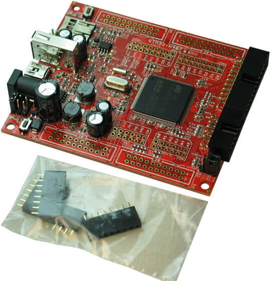
The OLIMEX-STM32-H407 is open source hardware and is based on the STMicroelectronics STM32F407ZG ARM Cortex-M4 CPU.
OLIMEX-STM32-H407
Hardware
Information about the board can be found at the OLIMEX-STM32-H407 website and OLIMEX-STM32-H407 user manual. The ST STM32F407ZG Datasheet contains the processor’s information and the datasheet.
Supported Features
The olimex_stm32_h407 board supports the hardware features listed below.
- on-chip / on-board
- Feature integrated in the SoC / present on the board.
- 2 / 2
-
Number of instances that are enabled / disabled.
Click on the label to see the first instance of this feature in the board/SoC DTS files. -
vnd,foo -
Compatible string for the Devicetree binding matching the feature.
Click on the link to view the binding documentation.
Pin Mapping
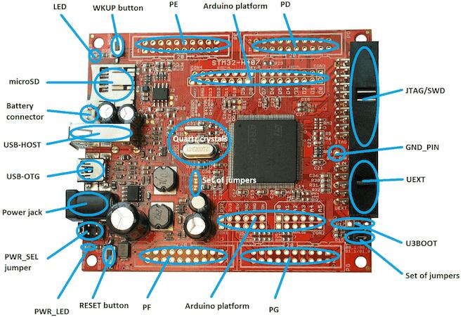
OLIMEX-STM32-H407 connectors
LED
LED (green) = PC13
PWR_LED (red) = power
External Connectors
JTAG/SWD debug
PIN # |
Signal Name |
Pin # |
Signal Name |
|---|---|---|---|
1 |
+3.3V |
11 |
|
2 |
+3.3V |
12 |
GND |
3 |
PB4 / TRST |
13 |
PB3 / TDO |
4 |
GND |
14 |
GND |
5 |
PA15 / TDI |
15 |
PB4 / TRST |
6 |
GND |
16 |
GND |
7 |
PA13 / TMS |
17 |
|
8 |
GND |
18 |
GND |
9 |
PA14 / TCK |
19 |
+5V_JTAG |
10 |
GND |
20 |
GND |
UEXT
PIN # |
Wire Name |
STM32F407 port |
|---|---|---|
1 |
+3.3V |
|
2 |
GND |
|
3 |
PC6/USART6_TX |
PC6 |
4 |
PC7/USART6_RX |
PC7 |
5 |
PB8/I2C1_SCL |
PB8 |
6 |
PB9/I2C1_SDA |
PB9 |
7 |
PC2/SPI2_MISO |
PC2 |
8 |
PC3/SPI2_MOSI |
PC3 |
9 |
PB10/SPI_SCK/UART3_TX |
PB10 |
10 |
RB7/UEXT_CS |
PB7 |
Arduino Headers
CON1 power
Pin |
Signal Name |
STM32F407 Pin# |
|---|---|---|
RST |
RESET |
25 |
3V3 |
VCC (3V3) |
N/A |
5V |
VDD (5V) |
N/A |
GND |
GND |
N/A |
GND |
GND |
N/A |
VIN |
VIN |
N/A |
CON2 analog
Pin |
Signal Name |
STM32F407 Pin# |
|---|---|---|
A0 |
PC0 |
26 |
A1 |
PC1 |
27 |
A2 |
PB0 |
46 |
A3 |
PB1 |
47 |
A4 |
PC4 |
44 |
A5 |
PC5 |
45 |
CON3 digital
Pin |
Signal Name |
STM32F407 Pin# |
|---|---|---|
D0 |
PA3/USART2_RX |
37 |
D1 |
PA2/USART2_TX |
36 |
D2 |
PG7 |
92 |
D3 |
PG8 |
93 |
D4 |
PG12 |
127 |
D5 |
PG13 |
128 |
D6 |
PG14 |
129 |
D7 |
PG15 |
132 |
CON4 digital
Pin |
Signal Name |
STM32F407 Pin# |
|---|---|---|
D8 |
PA1 |
35 |
D9 |
PB11 |
70 |
D10 |
PA4 |
40 |
D11 |
PA7 |
43 |
D12 |
PA6 |
42 |
D13 |
PA5 |
41 |
GND |
AGND |
31 |
AREF |
AREF |
32 |
PD
PIN # |
Signal Name |
Pin # |
Signal Name |
|---|---|---|---|
1 |
+3.3V |
11 |
PD8 |
2 |
GND |
12 |
PD9 |
3 |
PD0 |
13 |
PD10 |
4 |
PD1 |
14 |
PD11 |
5 |
PD2/SD_CMD |
15 |
PD12 |
6 |
PD3 |
16 |
PD13 |
7 |
PD4 |
17 |
PD14 |
8 |
PD5 |
18 |
PD15 |
9 |
PD6 |
19 |
+5V |
10 |
PD7 |
20 |
GND |
PE
PIN # |
Signal Name |
Pin # |
Signal Name |
|---|---|---|---|
1 |
+3.3V |
11 |
PE8 |
2 |
GND |
12 |
PE9 |
3 |
PE0 |
13 |
PE10 |
4 |
PE1 |
14 |
PE11 |
5 |
PE2 |
15 |
PE12 |
6 |
PE3 |
16 |
PE13 |
7 |
PE4 |
17 |
PE14 |
8 |
PE5 |
18 |
PE15 |
9 |
PE6 |
19 |
+5V |
10 |
PE7 |
20 |
GND |
PF
PIN # |
Signal Name |
Pin # |
Signal Name |
|---|---|---|---|
1 |
+3.3V |
11 |
PF8 |
2 |
GND |
12 |
PF9 |
3 |
PF0 |
13 |
PF10 |
4 |
PF1 |
14 |
PF11 |
5 |
PF2 |
15 |
PF12 |
6 |
PF3 |
16 |
PF13 |
7 |
PF4 |
17 |
PF14 |
8 |
PF5 |
18 |
PF15 |
9 |
PF6 |
19 |
+5V |
10 |
PF7 |
20 |
GND |
PG
PIN # |
Signal Name |
Pin # |
Signal Name |
|---|---|---|---|
1 |
+3.3V |
11 |
PG8/D3 |
2 |
GND |
12 |
PG9 |
3 |
PG0 |
13 |
PG10 |
4 |
PG1 |
14 |
PG11 |
5 |
PG2 |
15 |
PG12/D4 |
6 |
PG3 |
16 |
PG13/D5 |
7 |
PG4 |
17 |
PG14/D6 |
8 |
PG5 |
18 |
PG15/D7 |
9 |
PG6 |
19 |
+5V |
10 |
PG7/D2 |
20 |
GND |
System Clock
OLIMEX-STM32-H407 has two external oscillators. The frequency of the slow clock is 32.768 kHz. The frequency of the main clock is 12 MHz. The processor can setup HSE to drive the master clock, which can be set as high as 168 MHz.
Programming and Debugging
The olimex_stm32_h407 board supports the runners and associated west commands listed below.
| flash | debug |
|---|
The OLIMEX-STM32-H407 board does not include an embedded debug tool interface. You will need to use ST tools or an external JTAG probe. In the following examples the Olimex ARM-USB-OCD-H is used.
If you have an external JTAG probe compliant with the default Zephyr OpenOCD
configuration, however, then applications for the olimex_stm32_h407 board
configuration can be built and flashed in the usual way (see
Building an Application and Run an Application for more details).
Flashing an application to the Olimex-STM32-H407
Connect the ARM-USB-OCD-H debugger to your host computer and to the JTAG port of the OLIMEX-STM32-H407 board. Then build and flash an application.
Here is an example for the Hello World application.
# From the root of the zephyr repository
west build -b olimex_stm32_h407 samples/hello_world
west flash
Run a serial host program to connect with your board:
$ minicom -D /dev/ttyUSB0
After resetting the board, you should see the following message:
***** BOOTING ZEPHYR OS v1.11.0 - BUILD: Mar 12 2018 03:12:40 *****
Hello World! arm
Debugging
Provided that you have a JTAG probe, you can debug an application in the usual way. Here is an example for the Hello World application.
# From the root of the zephyr repository
west build -b olimex_stm32_h407 samples/hello_world
west debug