YJ-17095
Overview
The Holyiot [1] YJ-17095 hardware features the Nordic Semiconductor nRF52832 ARM Cortex-M4 CPU and the following devices:
CLOCK
FLASH
GPIO
MPU
NVIC
PWM
RADIO (Bluetooth Low Energy)
RTC
Segger RTT (RTT Console)
WDT
The board does not contain peripherals for direct physical interaction, but it has an on-board 2.4 GHz antenna for Bluetooth Low Energy (BLE) communication. There are 11 GPIO pins accessible via solder pads on the board, in addition to pins for power supply and SWD programming. The Nordic Semiconductor Infocenter [2] contains the processor’s information and the datasheet. The boards measures 9.4mm by 9.25mm.
Hardware
The nRF52832 of the Holyiot YJ-17095 is clocked by an external crystal with a frequency of 32 MHz.
Supported Features
The holyiot_yj17095 board supports the hardware features listed below.
- on-chip / on-board
- Feature integrated in the SoC / present on the board.
- 2 / 2
-
Number of instances that are enabled / disabled.
Click on the label to see the first instance of this feature in the board/SoC DTS files. -
vnd,foo -
Compatible string for the Devicetree binding matching the feature.
Click on the link to view the binding documentation.
Connections and IOs
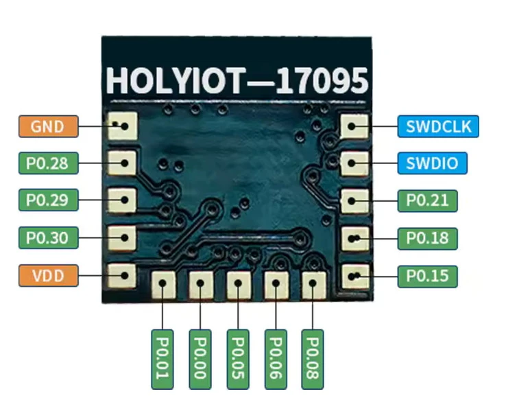
Holyiot YJ-17095 PCB and pin out (Credit: Holyiot)
Programming and Debugging
The holyiot_yj17095 board supports the runners and associated west commands listed below.
| flash | debug |
|---|
The boards can be programmed and debugged using an external programming and debugging tool, such as a Segger J-Link (see Building an Application and Run an Application for more details).
The following pins of the Segger J-Link must be connected to the following test pads on the PCB (see image):
VTref = VDD
GND = GND
SWDIO = SWDIO
SWCLK = SWCLK
Flashing
Follow the instructions in the Nordic nRF5x Segger J-Link page to install and configure all the necessary software. Further information can be found in Flashing. Then build and flash applications as usual (see Building an Application and Run an Application for more details).
Here is an example for the Blinky application. Since there is not LED mounted on the PCB the
toggling GPIO can be measured on P0.29 with a multimeter or an oscilloscope.
# From the root of the zephyr repository
west build -b holyiot_yj17095 samples/basic/blinky
west flash
Debugging
Refer to the Nordic nRF5x Segger J-Link page to learn about debugging Nordic nRF52x-based boards with a Segger debugger.
Testing Bluetooth Low Energy (BLE) connectivity
The easiest way to test the Bluetooth Low Energy (BLE) connectivity of the board is to build and flash the Periodic Advertising application.
# From the root of the zephyr repository
west build -b holyiot_yj17095 samples/bluetooth/periodic_adv
west flash