

Heimann HTPA Eval Board (rev0)
Overview
The Heimann HTPA Eval Board (rev0) is a development platform for the
Heimann Thermopile Sensor Array (HTPA) family sensors. Array sensors
range from 8x8 pixels to 160x120 pixels, each with calibrated per
pixel temperature output.
Zephyr support is available as htpa_eval board with different
soc variants: ATSAME70Q20B, ATSAME70Q21, and ATSAME70Q21B.
The default target shown below is ATSAME70Q20B.
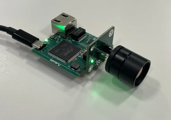
Heimann HTPA Eval Board (rev0)
Hardware
ATSAME70Q20B/Q21/Q21B ARM Cortex-M7 processor
12 MHz crystal oscillator => SOC @ 300MHz
32.768 kHz crystal oscillator
1 MiB or 2 MiB internal flash, depending on SoC variant
384 KiB RAM
1 MiB external SRAM
Ethernet interface
USB high-speed controller
RGB status LEDs
Camera power and indicator LEDs
User push-button
JTAG debug interface
Supported Features
The htpa_eval board supports the hardware features listed below.
- on-chip / on-board
- Feature integrated in the SoC / present on the board.
- 2 / 2
-
Number of instances that are enabled / disabled.
Click on the label to see the first instance of this feature in the board/SoC DTS files. -
vnd,foo -
Compatible string for the Devicetree binding matching the feature.
Click on the link to view the binding documentation.
Connections and IOs
UART0 is routed as the Zephyr console on this board. For board-specific connector and signal details, refer to the board schematic and hardware documentation.
System Clock
The ATSAME70 MCU is configured to use the 12 MHz external oscillator on the board with the on-chip PLL to generate a 300 MHz system clock.
Programming and Debugging
The htpa_eval board supports the runners and associated west commands listed below.
| flash | debug |
|---|
ROM and Boot Behavior
Factory-new SAME70 devices boot the SAM-BA [3] boot loader from ROM rather
than the flashed image. Boot selection is controlled by the GPNVM1
(General-Purpose NVM bit 1) flag:
GPNVM1 = 0 boots the ROM SAM-BA loader
GPNVM1 = 1 boots from flash
If GPNVM0 is set, the device cannot be programmed via the SAM-BA loader. A full chip erase is required, which clears the flash and GPNVM bits. Note: J-Link (the preferred flash option) can program and debug at all time.
OpenOCD and J-Link
The recommended flashing path uses the OpenOCD tool [1] together with a J-Link [2] debug probe. This path automatically sets GPNVM1 to 1 after programming, so the device boots the flashed image on reset.
Flashing the Zephyr project through OpenOCD requires the OpenOCD tool [1], which is built into Zephyr.
Flashing
Build and flash the Hello World application for the ATSAME70Q20B variant:
# From the root of the zephyr repository
west build -b htpa_eval/same70q20b samples/hello_world
west flash
The other supported variants are
htpa_eval/same70q21andhtpa_eval/same70q21b.Connect your serial terminal to the board console at 115200 8N1.
You should see
Hello World! htpa_evalin your terminal.
SAM-BA CLI
The board also supports SAM-BA uploads over the external UART interface. This path is useful when you want to work without a debug probe.
Before using the SAM-BA CLI, assert the board’s flash erase jumper so the
device can be erased and recovered if needed. The flash erase signal is
PB12. The board’s R7 resistor can be shorted while the board is
booting to trigger the flash erase sequence. After the erase sequence is
complete, you can upload the image with the SAM-BA command-line tools over
the board’s UART0 serial connection.
Debugging
You can debug an application in the usual way. Here is an example for the Hello World application.
# From the root of the zephyr repository
west build -b htpa_eval/same70q20b samples/hello_world
west debug